
Perpendicular magnetic recording medium and a manufacturing method for the same

Inactive Publication Date: 2001-11-08
FUJI ELECTRIC CO LTD
View PDF0 Cites 28 Cited by
  • Summary
  • Abstract
  • Description
  • Claims
  • Application Information

AI Technical Summary

Benefits of technology

[0005] The object of the present invention is to provide a perpendicular magnetic recording medium having an anti-ferromagnetic layer that prevents magnetic domain wall formation of the soft magnetic layer. A further object of the present invention is to provide a manufacturing method for this perpendicular magnetic recording medium whereby mass production is conducted easily.
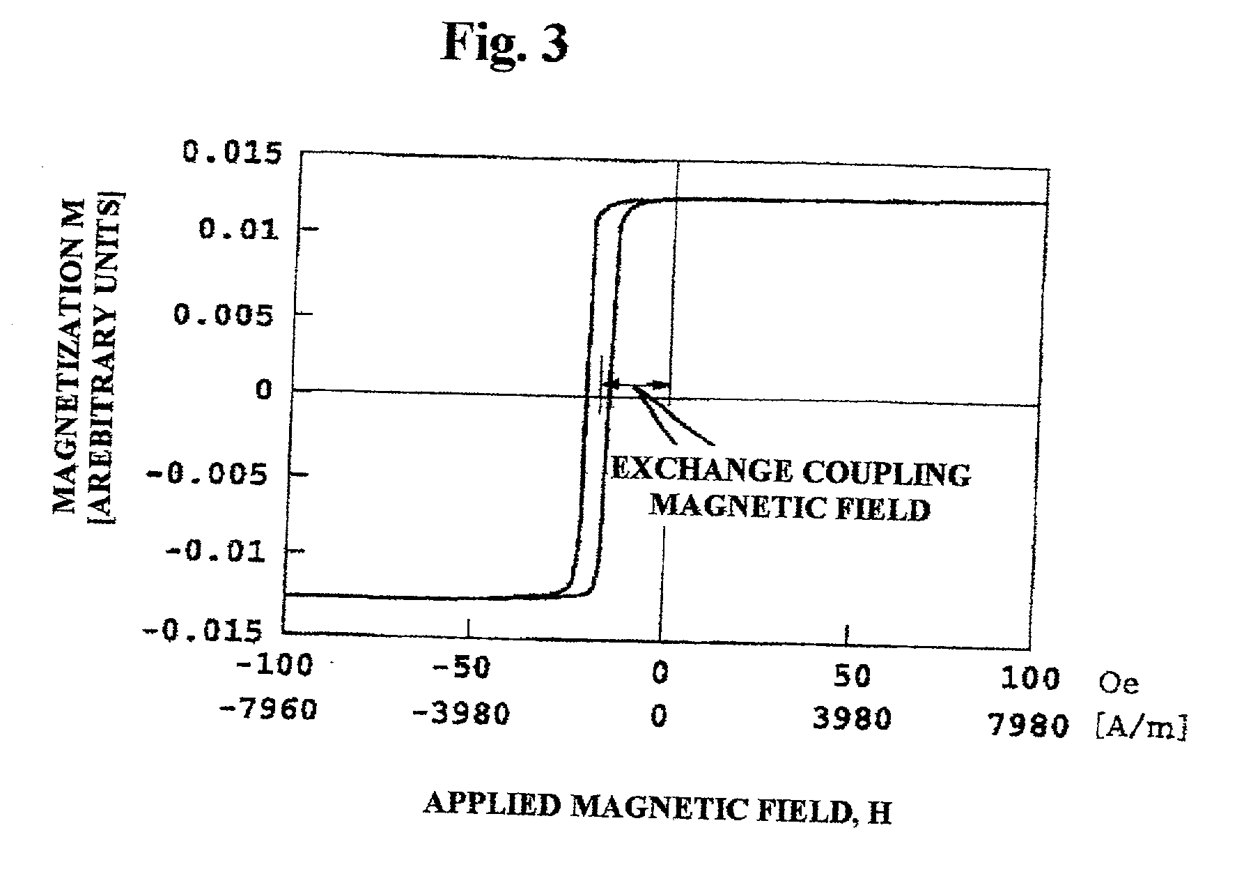
[0007] When manufacturing this magnetic recording medium, a magnetic field of 796 A / m (10 Oe) or greater is applied in the radial direction of the substrate during the film formation of at least the anti-ferromagnetic layer and the soft magnetic layer. This produces a suitable amount of exchange coupling without requiring heat treatment or the like after film formation. The domain walls of the soft magnetic layer is effectively controlled.
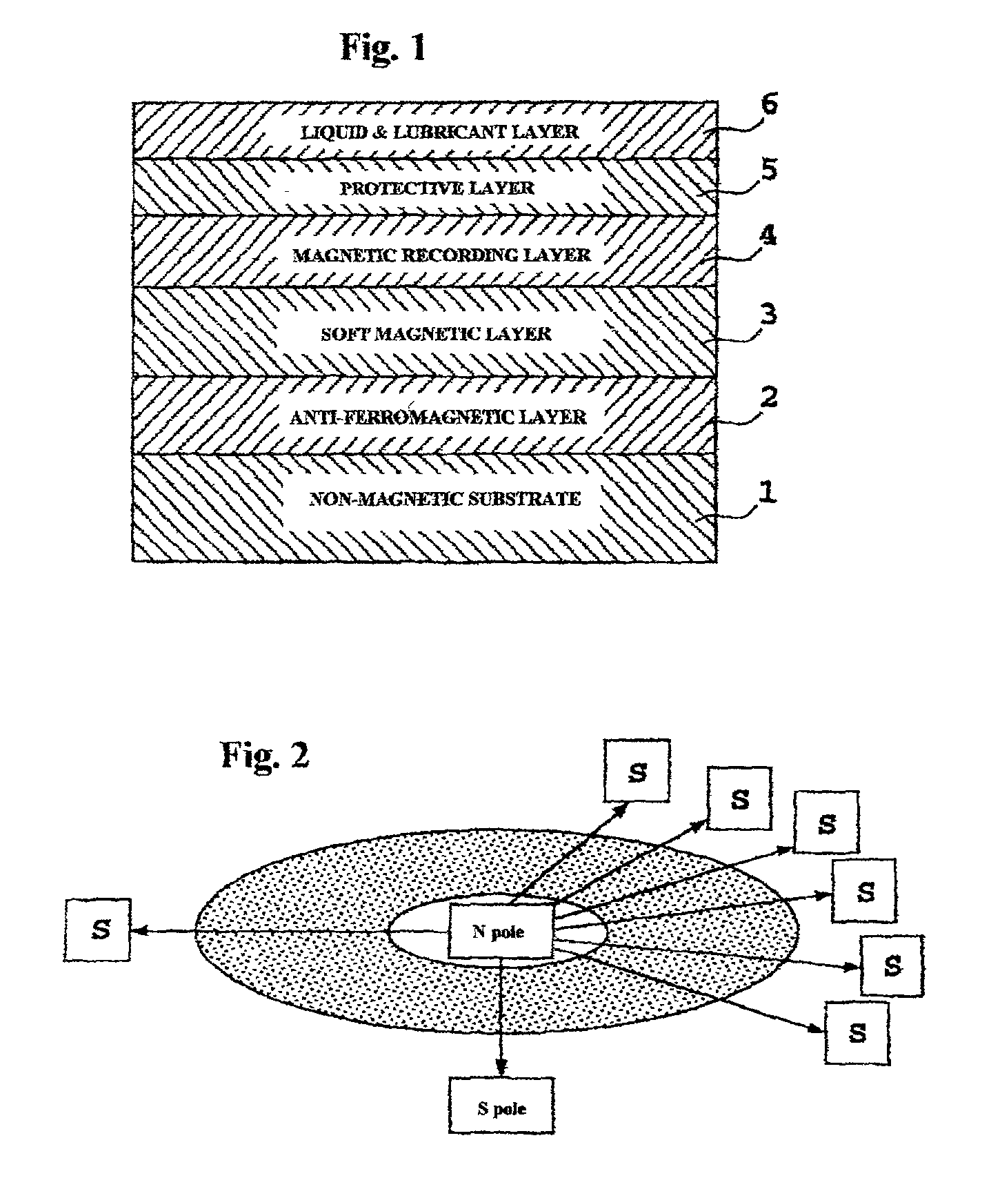
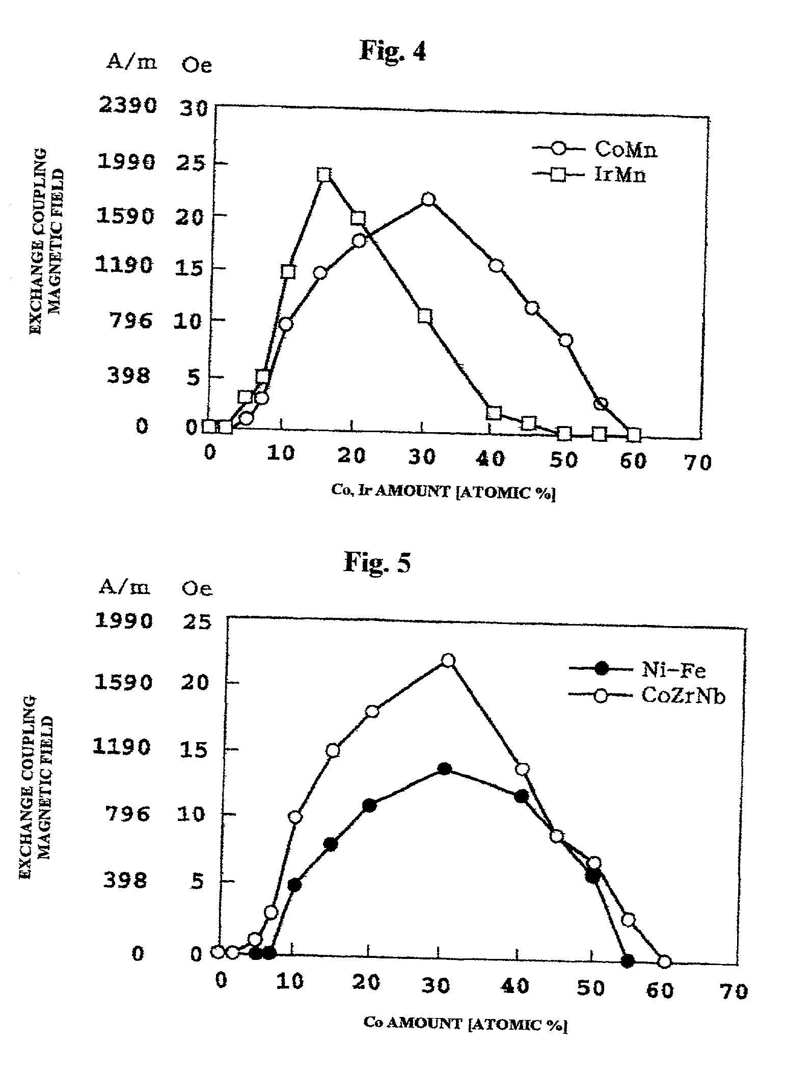
[0017] Anti-ferromagnetic layer 2 is constructed from an Mn alloy containing at least Co at 10 atomic % or greater and 50 atomic % or less (in other words, Co.sub.10-50Mn.sub.50-90), or an Mn alloy containing at least Ir at 10 atomic % or greater and 30 atomic % or less (in other words, Ir.sub.10-30Mn.sub.70-90). Other metals (for example at around 5 atomic %) can be added to this CoMn alloy and IrMn alloy as long as they do not negatively impact the anti-ferromagnetic layer properties. In contrast with the PdMn, PtMn, NiMn alloys described in Japanese Laid-Open Patent Publication Number 10-214719, by using the CoMn alloy or IrMn alloy of the present invention, heat treatment after film formation is unnecessary. The magnetic domain wall formation of the soft magnetic layer is controlled or, in other words suppressed, solely by the magnetic field applied during film formation. As a result, the production properties of the perpendicular magnetic recording medium is greatly improved. The film thickness of anti-ferromagnetic layer 2 is not limited, but in order to have a suitable degree of exchange coupling and in order to be suitable for mass production, a thickness of around 5 nm.about.30 nm is preferred. Furthermore, in order to control the film structure of anti-ferromagnetic layer 2, a thin film for structural control, for example a Cu film or the like, can be formed between non-magnetic substrate 1 and anti-ferromagnetic layer 2.
[0018] For soft magnetic layer 3, NiFe alloy, Sendust (FeSiAl) alloy and the like can be used, but the use of an amorphous Co alloy is preferred. By adding Zr, Nb, Ta, Hf, Ti, and / or W to the Co, an amorphous Co alloy is obtained. Amorphous alloys that are suitable for use in the present invention include CoZrNb, CoZrHf, and CoHfTa, and the like. CoZrNb is particularly preferred. When using CoZrNb, the effectiveness of the present invention, in other words, the effectiveness in controlling the magnetic domain wall of the soft magnetic layer, is maximized. When using CoZrNb alloy in the present invention, it is preferable to have 5.about.20 atomic % of Zr and 3.about.15 atomic % of Nb. The optimal value for the film thickness of soft magnetic layer 3 changes depending on the structure and properties of the magnetic head that is used for recording, but from the standpoint of being compatible with production, it is preferable to have a thickness of 10 nm or greater and 300 nm or less.

Problems solved by technology

This is extremely disadvantageous for mass production.

Method used


Image

  • Perpendicular magnetic recording medium and a manufacturing method for the same
  • Perpendicular magnetic recording medium and a manufacturing method for the same
  • Perpendicular magnetic recording medium and a manufacturing method for the same

Examples


embodiment 1

[0029] A sample for measuring the exchange coupling magnetic field was made in the same manner as Embodiment 1, except that, when forming the soft magnetic layer, a soft magnetic layer of a NiFe alloy was formed using a Ni.sub.78Fe.sub.22 alloy target. The exchange coupling magnetic field was measured. In addition, the anti-ferromagnetic layer was made using several CoMn alloy targets with differing compositions.

[0030] Referring to FIG. 5, the change in the value of the exchange coupling magnetic field with respect to the composition (Co content) of the CoMn anti-ferromagnetic layer is shown. For comparison, the change in the value of the exchange coupling magnetic field in the sample (soft magnetic layer of CoZrNb alloy) of Embodiment 1 is also shown. The exchange coupling magnetic field, when using NiFe alloy as the soft magnetic layer, was small compared to when a CoZrNb amorphous alloy was used. This confirms that a higher exchange coupling magnetic field is obtained using a CoZ...

embodiment 3

[0031] [Embodiment 3]

[0032] A sample for measuring the exchange coupling magnetic field was made in the same manner as Embodiment 1, except that the value of the magnetic field applied during film formation of the anti-ferromagnetic layer and the soft magnetic layer was varied, and a Co.sub.30Mn.sub.70 alloy target was used for formation of the anti-ferromagnetic layer.

[0033] Referring to FIG. 6, the relationship between the strength of the magnetic field applied during film formation and the strength of the exchange coupling magnetic field of the resulting sample is shown. It is seen that an adequate exchange coupling magnetic field is obtained when the magnetic field applied during film formation is 796 A / m (10 Oe) or greater. With the device used, the plasma discharge during sputtering became unstable when the applied magnetic field was 23900 A / m (300 Oe) or greater, and film formation could not be conducted.

[0034] As described above, according to the present invention, by using ...


PUM


Abstract

A perpendicular magnetic recording medium is formed of a soft magnetic layer, an anti-ferromagnetic layer, a magnetic recording layer, a protective layer, and a liquid lubricant layer deposited in that order on a non-magnetic substrate. The anti-ferromagnetic layer is a Mn alloy containing at least Co at 10 atomic % or greater and 50 atomic % or less or a Mn alloy containing at least Ir at 10 atomic % or greater and 30 atomic % or less. A radial magnetic field is applied during formation of the anti-ferromagnetic layer and the soft magnetic layer. Exchange coupling with the anti-ferromagnetic layer controls magnetic domain walls of the soft magnetic layer. The need for heat treatment after film formation is eliminated.

Description

BACKGROUND TO THE PRESENT INVENTION[0001] The present invention relates to a perpendicular magnetic recording medium that is mounted onto various magnetic recording devices and a manufacturing method for the same.[0002] Instead of the longitudinal magnetic recording system of the prior art, a perpendicular magnetic recording system has been gathering attention as a technique for increasing densities of magnetic recordings. A perpendicular magnetic recording medium is constructed from a magnetic recording layer of a hard magnetic material and a backing layer of a soft magnetic material. The backing layer has the function of concentrating the magnetic flux that is generated by the magnetic head that is used in recording to the recording layer. Among the noises that are of concern in a perpendicular recording medium with this structure, spike noise is known to be a result of a magnetic domain wall formed in the soft magnetic layer that is the backing layer. As a result, in order to hav...

Claims


Application Information

Patent Timeline
IPC IPC(8): G11B5/66G11B5/667G11B5/738G11B5/852
CPCG11B5/66Y10T428/12465Y10T428/12861Y10S428/90
Inventor UWAZUMI, HIROYUKISAKAI, YASUSHIATAKA, TOYOJI
Owner FUJI ELECTRIC CO LTD
Learn More