
Method for three-dimensional solid graphic generation and record medium of three-dimensional solid graphic generation

a technology of three-dimensional solids and graphic data, applied in the direction of 2d-image generation, static indicating devices, instruments, etc., can solve the problems of inability to express movable solids with their shape changing from moment to moment, and achieve the effect of suppressing the amount of data for describing the generation and the display of three-dimensional solids

Inactive Publication Date: 2001-11-22
NIITSU YASUSHI
View PDF0 Cites 3 Cited by
  • Summary
  • Abstract
  • Description
  • Claims
  • Application Information

AI Technical Summary

Benefits of technology

[0012] Namely, according to this aspect, the use of the variable makes it possible to suppress an amount of data lower when generating the graphics while changing the shape of the graphics successively. Moreover, the generated graphics are displayed successively, thereby allowing the solid to be expressed with its shape changing. Further, when the graphics are generated while moving and changing its shape successively, it is also possible to suppress the amount of data lower. Furthermore, a movable solid can be expressed by displaying these graphics successively.
[0030] Further, the amount of data for describing the generation and the display of the three-dimensional solid can be suppressed further lower by using the variable, the repetition control and the conditional branch control. Also, similarly to the above aspect of the present invention, the expression of the solid with its shape changing and the expression of the movable solid are made possible by employing the simple command string in the text file as the graphic data.

Problems solved by technology

However, in the conventional expressing form, the expression of the solid with its shape changing from moment to moment and the expression of the movable solid are impossible even by the parametric representation.

Method used


Image

  • Method for three-dimensional solid graphic generation and record medium of three-dimensional solid graphic generation
  • Method for three-dimensional solid graphic generation and record medium of three-dimensional solid graphic generation
  • Method for three-dimensional solid graphic generation and record medium of three-dimensional solid graphic generation

Examples


first embodiment

[0039] Hereinafter, a method for three-dimensional solid graphic generation and a record medium of three-dimensional solid graphic generation according to the present invention will be explained with reference to the drawings.

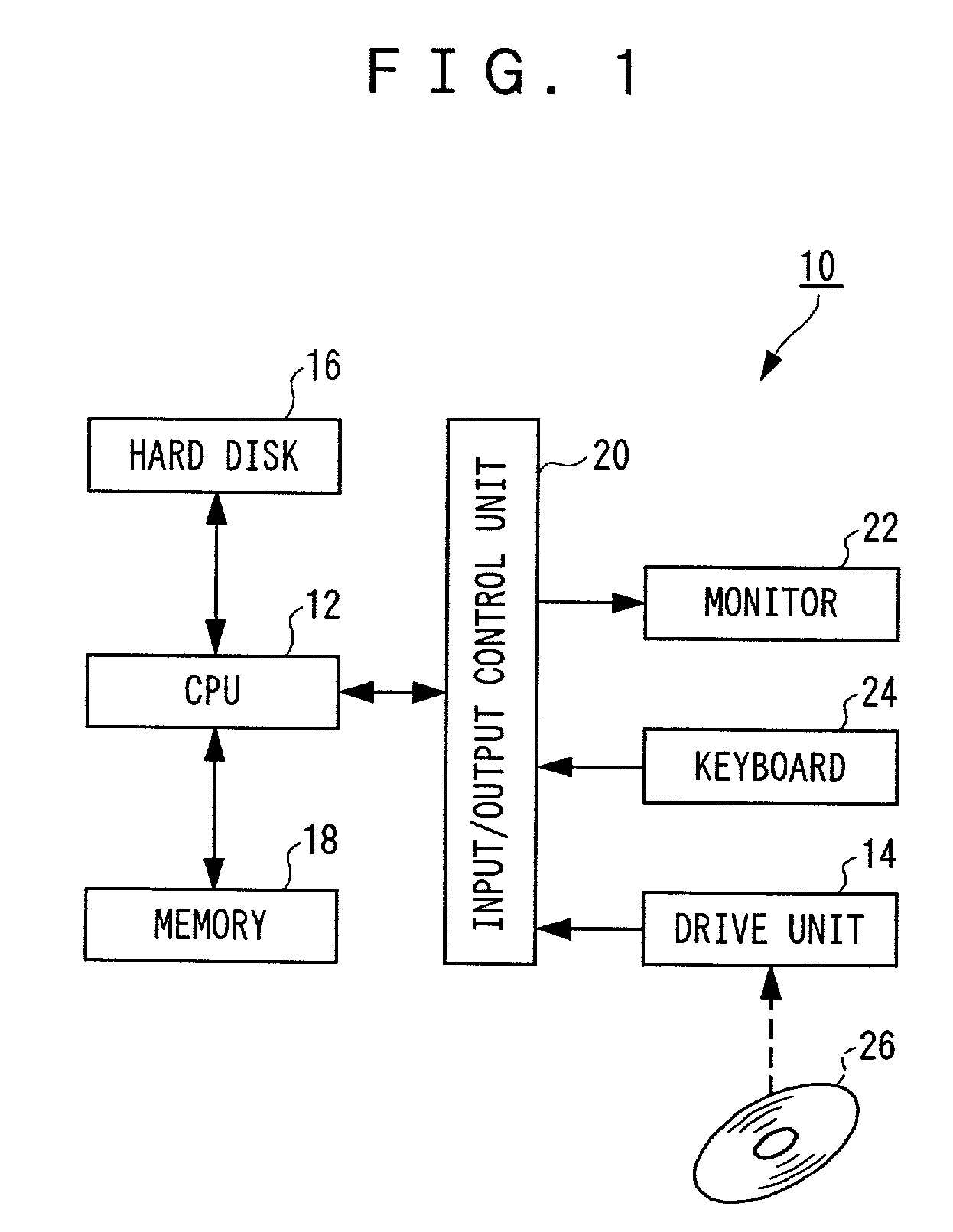
[0040] A block diagram of a computer 10 as a three-dimensional solid graphic generating device according to this embodiment is shown in FIG. 1. The computer 10, as shown in the drawing, includes a CPU (Central Processing Unit) 12 as an arithmetic unit which is capable of executing programs such as generation and display of a three-dimensional solid, a drive unit 14 which is capable of reading data, the program and the like from the record mediums such as a CD-ROM 26 and a floppy disk, a hard disk 16 in which data, the program and the like read by the drive unit 14 are installed and stored, and a memory 18 such as RAM as a storage unit which is capable of inputting / outputting data and the like to / from the CPU 12, as basic components, respectively.

[0041] Further,...

example 1

[0050]

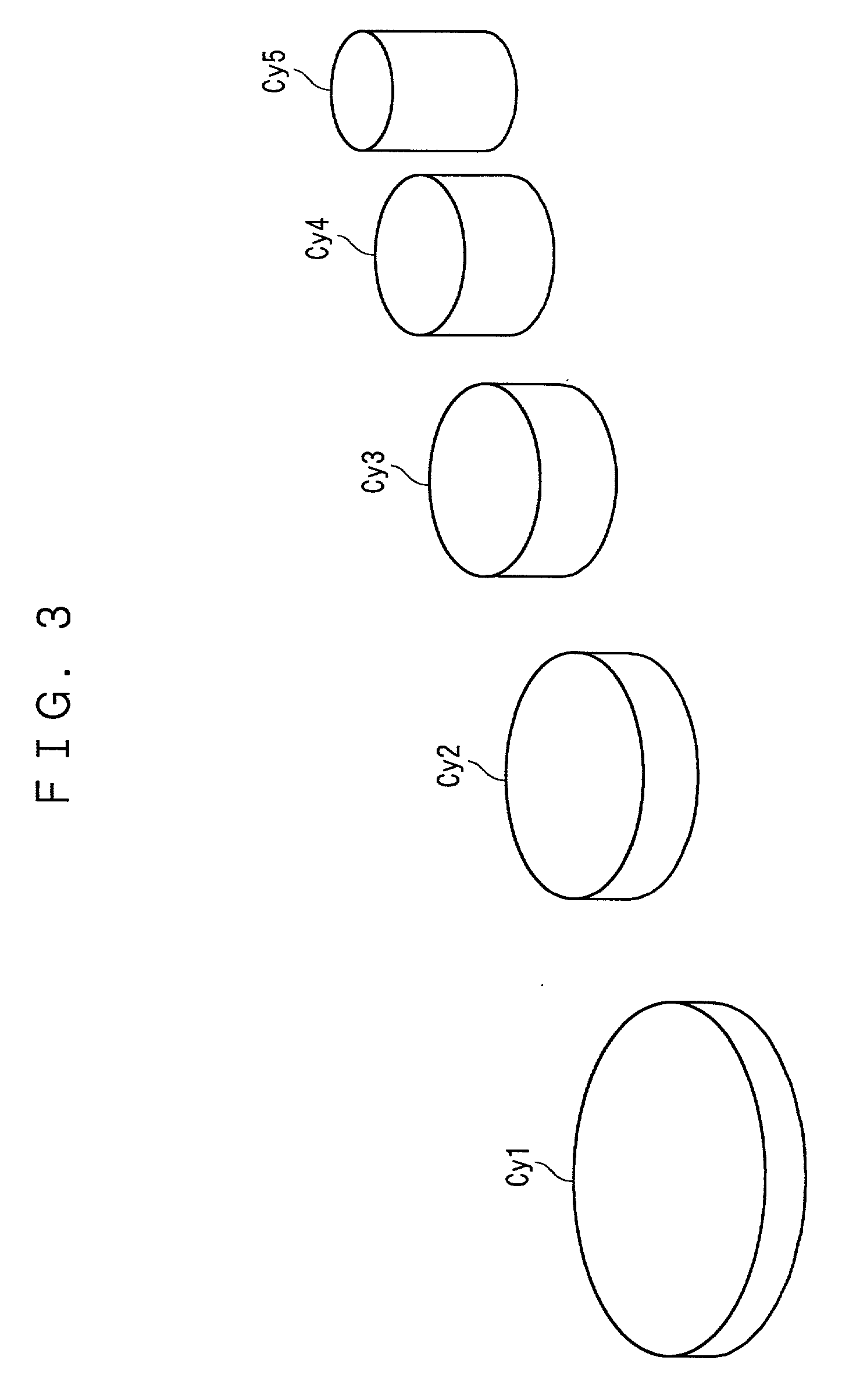
1 H=2; R=12; M=10 Group XX0 { Repeat 5 { Cylinder Cy% R, H Move Cy% 0, M, 0 R=R-2; H=H+2; M=M+R } } Display Group XX0

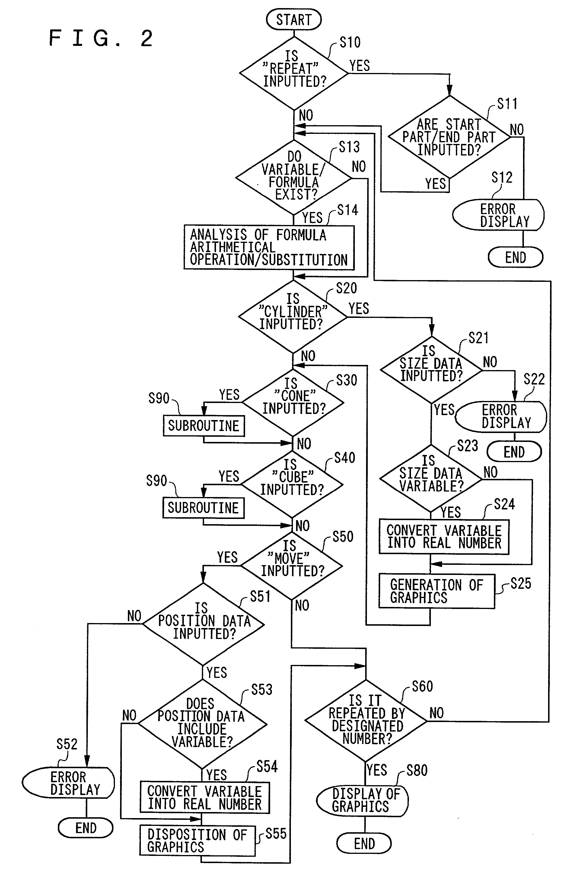
[0051] By pressing a return key of the keyboard 24, the aforementioned command groups are inputted in the CPU 12 via the input / output control unit 20 and the execution of the software for the three-dimensional solid is started as shown in FIG. 2 so that each command string is processed in the CPU 12 of the computer 10.

[0052] When this processing is started, it is first decided whether "Repeat" as the processing command of the repetition control is inputted or not in a step S10, and if it is not inputted, processing continues by moving to a next step S13. However, in this example, since the decision can be made that "Repeat" is inputted in the step S10, it is decided whether the start part and the end part which show the range of the repetition control are inputted or not in a step S11. In other words, it is decided whether "{" as a command of the start part and ...

example 2

[0070]

2 N=12; R=10; H=22 Cone Body N, R, H Xcolor Body 1, 1, 1 C=5 Repeat C { R=R-1; H=H-4; Cone Co% N, R, H Move Co% 0, M, 0 Body=Body+Co% } Display eye0 Body

[0071] By pressing the return key of the keyboard 24, the aforementioned command groups are inputted in the CPU 12 via the input / output control unit 20 and the execution of the software for the three-dimensional solid is started as shown in FIG. 4 so that each command string is processed in the CPU 12 of the computer 10.

[0072] When this processing is started, it is first decided whether "Repeat" as the processing command of the repetition control is inputted or not in a step S10, and if it is not inputted, processing continues by moving to a next step S13. However, also in this example, since the decision can be made that "Repeat" is inputted in the step S10, it is decided whether the start part and the end part showing the range of the repetition control are inputted or not in a step S11, similarly to Example 1.

[0073] If at l...


PUM


Abstract

A method for three-dimensional solid graphic generation: First, a basic graphic command and a variable showing a size of the graphics are inputted into an input unit as graphic data and a condition for changing the variable is inputted into the input unit. Next, a three-dimensional solid graphics is generated in an arithmetic unit by changing the size of the graphics based on the condition for changing the variable to change the shape of the graphics. Thereby, it becomes possible to express a solid with its shape changing and to express a movable solid.

Description

BACKGROUND OF THE INVENTION[0001] 1. Field of the Invention[0002] This invention relates to a method for three-dimensional solid graphic generation and a record medium of three-dimensional solid graphic generation which are capable of expressing a solid by changing its shape and expressing a movable solid, and intended preferably to be used for schooling.[0003] 2. Description of the Related Art[0004] As conventional file formats for expressing a solid in a three-dimensional manner, a VRML format which is a standard expressing form of a three-dimensional solid in the Internet, a standard CAD file format called IGES or STEP, file formats which are established by respective CAD manufactures such as a DXF file format and so on have been hitherto known. However, these expressing forms of the three-dimensional solid express the solid in a fixed condition.[0005] Meanwhile, part of an expressing method of a binary format such as a preprocessor of StressCheck as finite element analysis softw...

Claims


Application Information

Patent Timeline
IPC IPC(8): G06F17/50G06F3/14G06T17/10
CPCY10S715/964G06T17/10G06T2219/2021G06T2219/2016G06T19/20
Inventor NIITSU, YASUSHI
Owner NIITSU YASUSHI
Learn More