Ratchet and cam buckle tensioning assembly and method for using same

a technology of ratchet buckle and cam buckle, which is applied in the direction of wire tools, transportation items, manufacturing tools, etc., can solve the problems of limited length of lashing strap, large number of tensioning operations to be performed, and oftentimes significant time required to perform numerous manipulations of ratchet buckles. achieve the effect of quick and convenient pre-tension

Inactive Publication Date: 2001-11-29
WRIGHT JEFFREY DAVID MR
View PDF0 Cites 43 Cited by
  • Summary
  • Abstract
  • Description
  • Claims
  • Application Information

AI Technical Summary

Benefits of technology

[0009] The present invention is a ratchet and cam buckle tensioning assembly, interposed between a lashing strap tensioned by the ratchet buckle and a lead strap tensioned by the cam buckle. The tensioning assembly enables an operator to quickly and conveniently pre-tension the lashing and lead straps by removing an un-tensioned length of the lead strap without having to operate the ratchet buckle. This advantageously enables the operator to utilize the ratchet buckle to tension the straps only when the requisite tensioning force cannot be provided by an unaided operator. That is, the ratchet buckle may be operated only to tension a lashing strap that has been pre-tensioned with the cam buckle, thereby facilitating the use of the combined assembly. As a result, the present invention saves an operator from having to operate the ratchet buckle multiple times to uptake slack in the lashing strap when the leveraged tensioning force provided by such a ratchet buckle is unnecessary.
[0012] In an alternative embodiment, the cam buckle includes a housing adapted to slidably receive the lead strap. The housing has a pressure plate with a first restraining surface over which the lead strap slides. Also included in the cam buckle is a pawl movably mounted to the housing. The pawl has a second restraining surface and is biased in an engaged position to restrain the lead strap between the first and second restraining surfaces so as to prevent movement of the lead strap in one or both directions. The pawl also may assume a disengaged position wherein the lead strap can move freely between the first and second restraining surfaces. In one embodiment, the cam buckle is unidirectional, preventing movement of the lead strap a single direction. Particularly, the pawl, when in the engaged position, prevents movement of the lead strap in a direction that loosens the lead strap while allowing movement of the lead strap in a direction that tensions the lead strap. In one specific embodiment, the housing has a rear portion facing toward the ratchet buckle and a front portion facing away from the ratchet buckle. The lead strap travels from the front portion to the rear portion of the housing to tension the lead strap and from the rear portion towards the front portion to loosed the lead strap. In this embodiment, the pawl is constructed and arranged to engage and prevent movement of the lead strap in a direction from the front portion of the housing toward the rear portion of the housing while allowing movement of the strap from the rear portion of the housing to the front portion of the housing.
[0017] In another embodiment, the cam buckle includes a pawl having a first strap restraining surface and a finger-actuated lever on a side of the pawl opposing the first strap restraining surface, and a pivot pin about which the pawl rotates. A housing defining a second strap restraining surface opposing the first strap restraining surface and having two substantially parallel sides members supporting the pivot pin. A torsion spring, disposed about one end of the pivot pin, has a torque sufficient to maintain securely the first retraining surface of the pawl against the first restraining surface of the housing so as to cause the retraining surfaces to simultaneously contact the lead strap therebetween. This prevents movement of the lead strap in a direction that loosens the lead strap while allowing movement of the lead strap in a direction that tightens the lead strap. Rotation of the pawl lever causes the first retraining surface to rotate away from second retraining surface.
[0019] In one embodiment, the pressure plate has a rear end facing toward the ratchet buckle reel and a front end facing away from said ratchet buckle reel, the lead strap traveling from the front end to the rear end of the pressure plate when the lead strap is tensioned, and from the rear end towards the front end of the pressure plate when the lead strap is loosened. The pawl engages and prevents movement of the lead strap in a direction from the front end of the pressure plate toward the rear end of the pressure plate while allowing movement of the strap from the rear end of the pressure plate to the front end of the pressure plate.
[0021] In addition to the above-noted advantages, certain embodiments of the present invention provide additional advantages. For example, the present invention can be handled rapidly, comfortably and safely even by an untrained operator. The invention also enables an operator to quickly release the tensioned load simply by releasing the cam buckle by simple movement of the pawl operating lever to place the pawl in its unengaged position. Furthermore, the tensioning assembly is readily removably or demountable from the object. Also, the present invention enables for the pre-tensioning of a strap in a desired position before securely fastening the strap with the ratchet buckle in a tightened and secured position.

Problems solved by technology

Although such ratchet buckles are quite effective in tensioning straps, there are a number of drawbacks associated with using conventional ratchet buckles under certain circumstances.
One such drawback of is that a limited length of the lashing strap is wrapped around the drum or reel of the ratchet buckle in response to a single tensioning operation.
As a result, a large number of tensioning operations must be performed to uptake lengths of the lashing strap.
This oftentimes requires significant time performing numerous manipulations of the ratchet buckle.
Another drawback manifests itself when the conventional ratchet buckles are secured and fully tensioned, restraining a load under a tensioned lashing strap.
It is often difficult to release the tension on the lashing strap to remove or adjust a secured load.
As a result, fragile loads are sometimes damaged in the process of loosening or de-mounting the lashing strap and ratchet buckle.

Method used


Image

  • Ratchet and cam buckle tensioning assembly and method for using same
  • Ratchet and cam buckle tensioning assembly and method for using same
  • Ratchet and cam buckle tensioning assembly and method for using same

Examples


Embodiment Construction

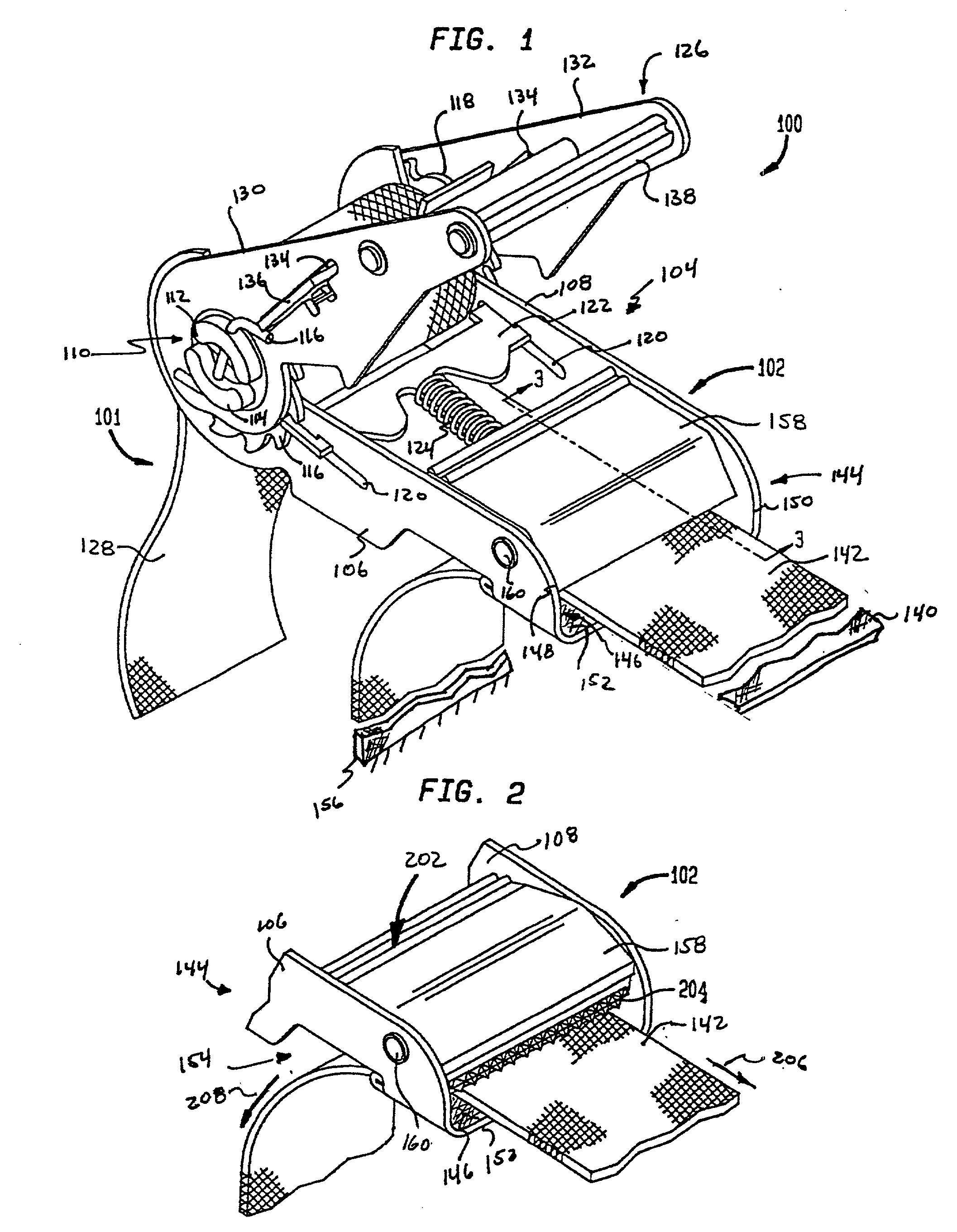
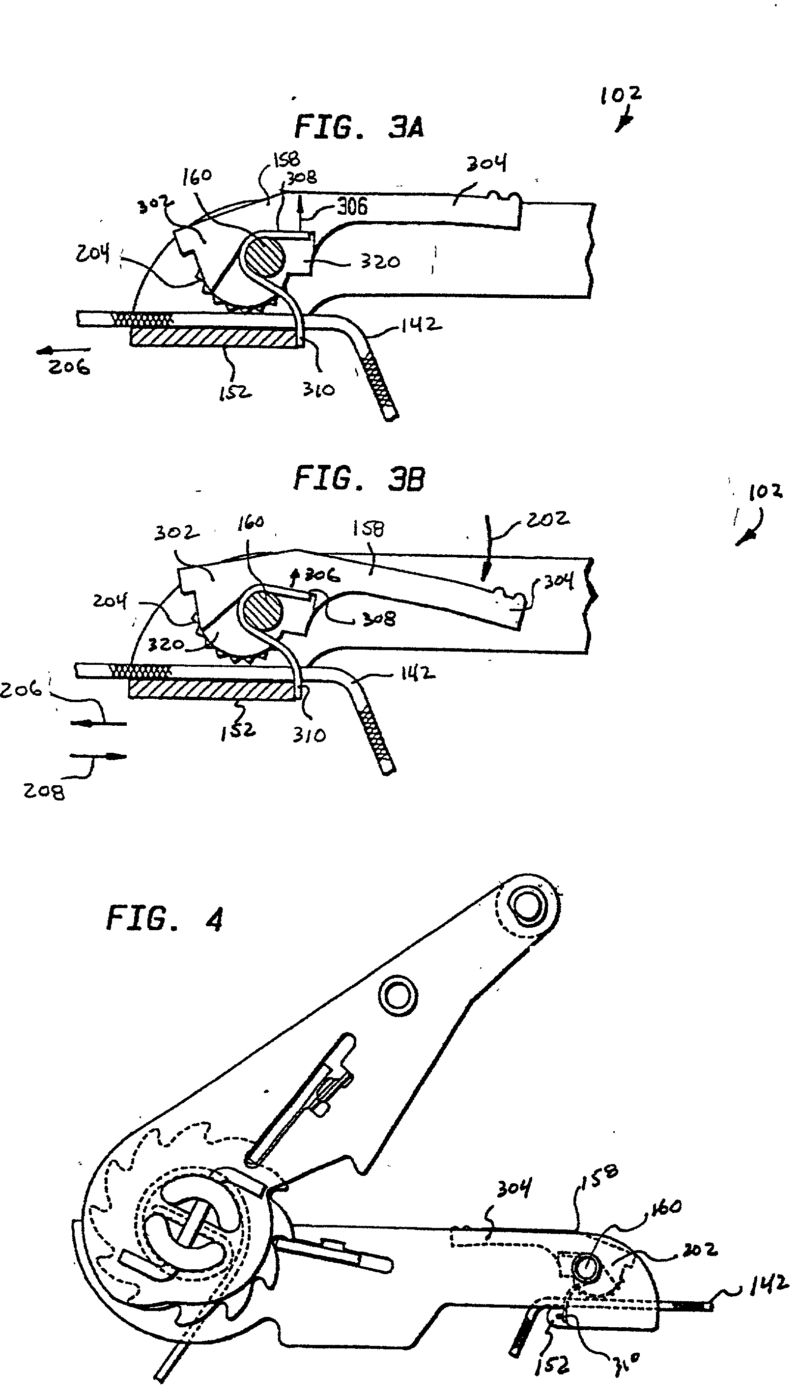
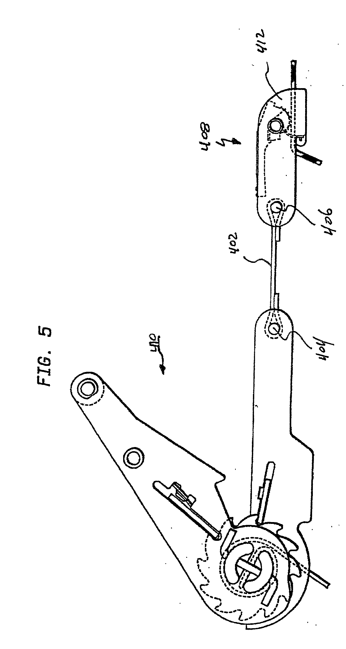
[0030] One aspect of the present invention is a ratchet and cam buckle tensioning assembly, interposed between a lashing strap tensioned by the ratchet buckle and a lead strap tensioned by the cam buckle, that enables an operator to quickly and conveniently pre-tension the lashing and lead straps by removing an un-tensioned length of the lead strap without having to operate the ratchet buckle. This enables the operator to utilize the ratchet buckle to tension the straps only when the requisite tensioning force cannot be provided by an unaided operator. This saves an operator from having to operate the ratchet buckle multiple times to uptake slack in the lashing strap when the leveraged tensioning force provided by such a ratchet buckle is unnecessary for such operations.

[0031] In the following description, the tensioning assembly is used in conjunction with flexible straps or belts. In particular, the disclosed embodiment of the tensioning apparatus can be harmoniously incorporated ...


PUM

PropertyMeasurementUnit
tensionsaaaaaaaaaa
torqueaaaaaaaaaa
movementaaaaaaaaaa

Abstract

A ratchet and cam buckle tensioning assembly or strap tensioner, interposed between a lashing strap tensioned by the ratchet buckle and a lead strap tensioned by the cam buckle. The invention enables an operator to quickly and conveniently pre-tension the lashing and lead straps by removing an un-tensioned length of the lead strap without having to operate the ratchet buckle. The tensioning assembly includes a ratchet buckle for tensioning the lashing strap in stepped increments and a cam buckle for slidingly adjusting the lead strap. The cam buckle housing and the ratchet buckle frame member are a unitary member, forming an single, integrated tensioning assembly. Alternately, the cam buckle is permanently attached adjacent to the ratchet buckle. The cam buckle includes a housing adapted to slidably receive the lead strap. The housing has a pressure plate with a first restraining surface, such as a friction surface, over which the lead strap slides. A pawl is movably mounted, such as by pivoting, to the housing. The pawl has a second restraining surface and is biased in an engaged position to restrain the lead strap between the first and second restraining surfaces so as to prevent movement of the lead strap in one or both directions. The pawl also may assume a disengaged position wherein the lead strap can move freely between the first and second restraining surfaces.

Description

RELATED APPLICATIONS[0001] This application claims the benefit of U.S. Provisional Application No. 60 / 087,270, filed May 29, 1998.BACKGROUND OF THE INVENTION[0002] 1. Field of the Invention[0003] The present invention relates generally to fastening devices and, more particularly, to ratchet buckles, strap tensioners, cargo retraining devices and the like for tightening and tensioning straps.[0004] 2. Related Art[0005] Ratchet buckles, also commonly referred to as cargo restraining devices and strap tensioners are commonly used for tightening and securing straps, ropes, chains or other tie-down tensioning lines. Generally, conventional ratchet buckles include a ratchet mechanism and a securing mechanism for retaining the strap in a tensioned condition. Conventional ratchet buckles for tightening and / or tensioning straps are described, for example, in U.S. Pat. Nos. 2,889,136, 4,185,360, 4,227,286, 4,199,182, 4,324,023, 4,570,305, 4,542,883, 5,282,296, and others.[0006] Although such ...

Claims


Application Information

Patent Timeline
Patent Type & Authority Applications(United States)
IPC IPC(8): B60P7/08
CPCY10T24/2175B60P7/083
Inventor LANDY, RICHARD
Owner WRIGHT JEFFREY DAVID MR
Why Eureka
Try Eureka