

Motor-driven device for adjusting a vehicle seat
- Summary
- Abstract
- Description
- Claims
- Application Information
AI Technical Summary
Benefits of technology
Problems solved by technology
Method used
Image

Examples
first embodiment
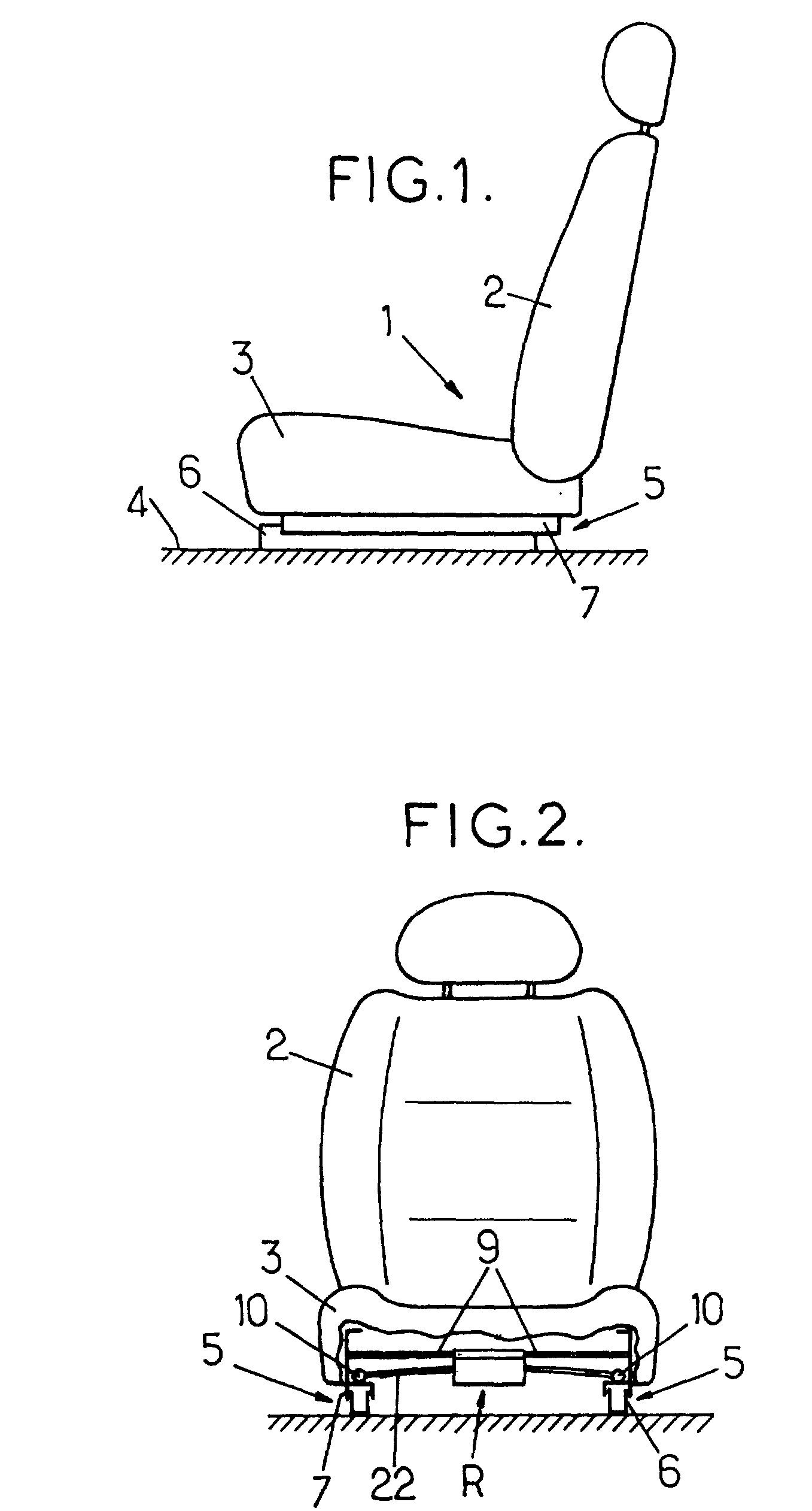
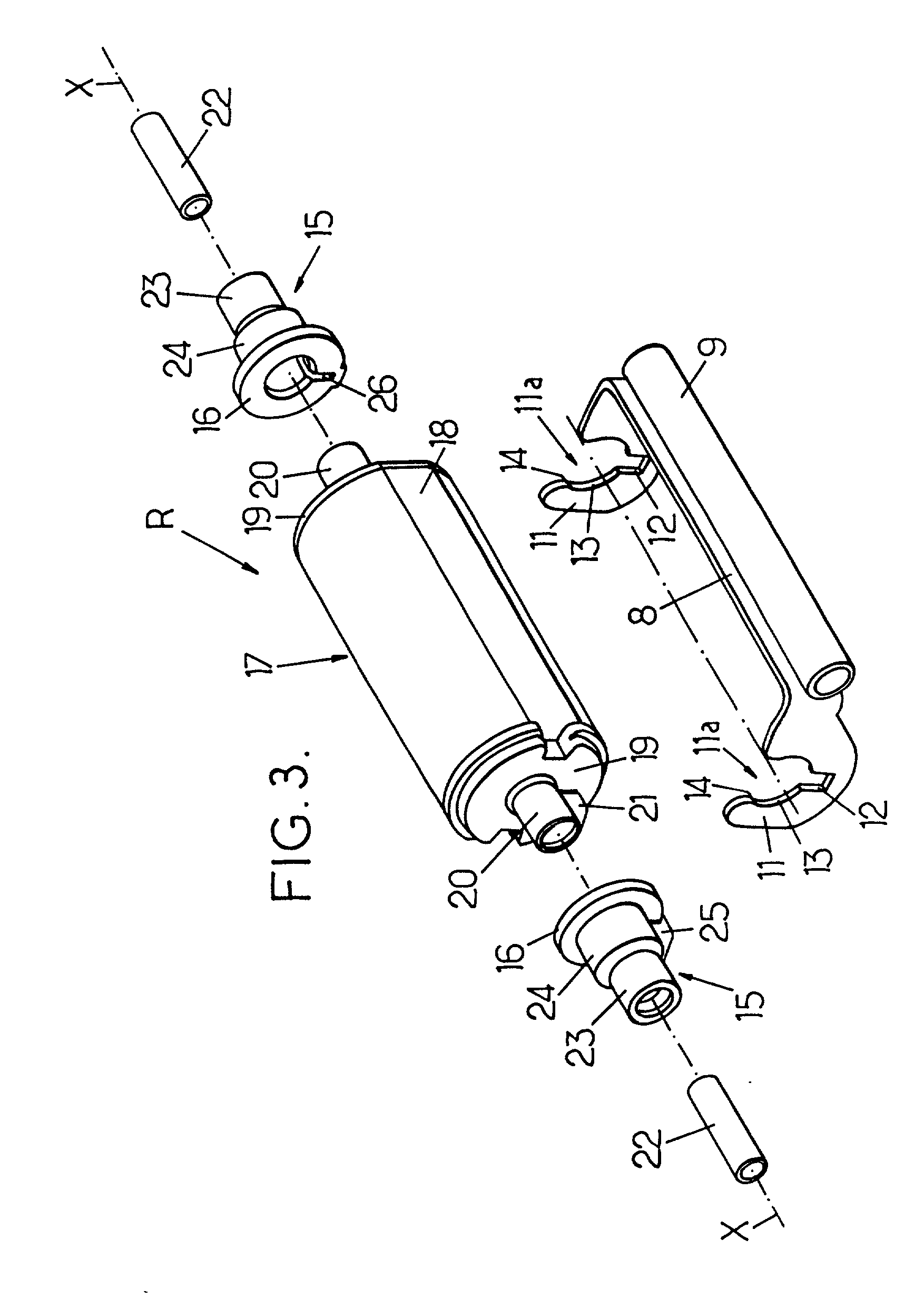
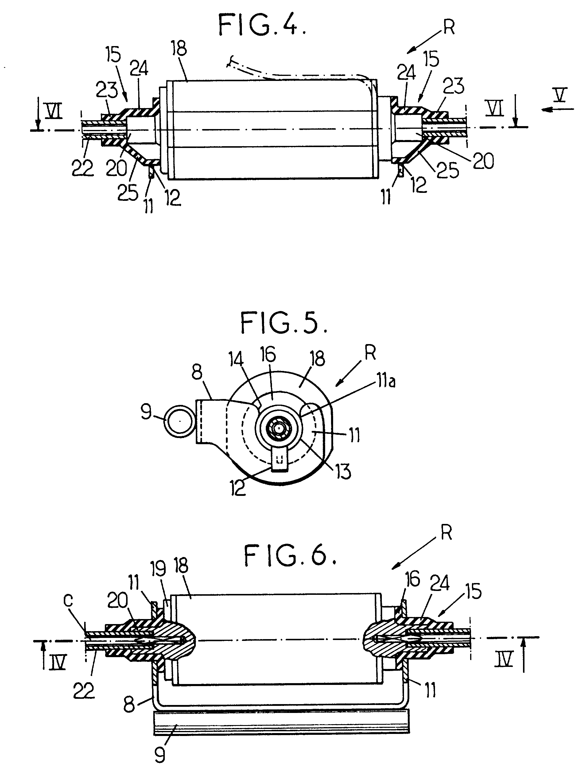
[0043] FIGS. 3 to 6 show the motor-driven adjustment device of the invention. The motor support 8 is generally U-shaped, having a middle or central portion fixed to the cross-member 9 and two lateral support plates 11 which form the ends of the support 8. The supports can be made of sheet metal, or indeed from injected plastics material.
[0044] The two support plates 11 of the support 8 are provided with respective cradles 11a for holding the electric motor 17 when it is assembled on the support.
[0045] To this end, the two endpieces 20 of the casing 18 are advantageously received so as to be prevented from rotating in elastically deformable sleeves 15 that are designed to be snap-fastened in respective ones of the cradles 11a of the support 8. Each elastically deformable sleeve has a first tubular portion 23 and a second tubular portion 24 adjacent thereto, the first tubular portion 23 having an outside diameter that is smaller than that of the second tubular portion 24. Each sleeve ...
second embodiment
[0055] FIGS. 7 to 11 show the motor-driven adjustment device of the invention. In this embodiment, the motor support 8 is likewise generally U-shaped, comprising a middle or central portion for fixing to the cross-member 9 (FIG. 1) and two lateral support plates 27 and 28 forming the ends of the support 8. The support plate 28 has a base portion 28b which extends substantially perpendicularly relative to the middle portion of the support 8, and an end portion 28a that slopes at an angle of about 50.degree. relative to the base portion 28b. As can be seen in FIG. 7, the cradle 11b formed on the support plate 28 comprises a window 11b with a closed outlet that is substantially identical to the outline of the sleeves 15 that is to be associated therewith. This sleeve 15 has a flat 24a on its second tubular portion 24. The window 11b also has a notch 29 for co-operating with the key 25 formed on the sleeve 15. The notch 29 is preferably made in the base portion 28b of the support plate ...
PUM
 Abstract
Description
Claims
Application Information