Method and circuit for driving display device

a display device and circuit technology, applied in static indicating devices, cathode-ray tube indicators, instruments, etc., can solve the problems of small deterioration of display contents, power consumption that cannot be effectively decreased in the partial display mode, and current display panels that have predivided display areas cannot meet this demand

Inactive Publication Date: 2001-12-20
SANYO ELECTRIC CO LTD
View PDF9 Cites 107 Cited by
  • Summary
  • Abstract
  • Description
  • Claims
  • Application Information

AI Technical Summary

Problems solved by technology

Current display panels that with predivided display areas cannot meet this demand.
As a result, power consumption cannot be effectively decreased in the partial display mode.
The use of the off-display data as the background display data results in very small deterioration of display contents.

Method used


Image

  • Method and circuit for driving display device
  • Method and circuit for driving display device
  • Method and circuit for driving display device

Examples


Embodiment Construction

[0079] A preferred embodiment (hereinafter referred to as the embodiment) according to the present invention will be explained below while referring to the attached drawings. [Basic Configuration]

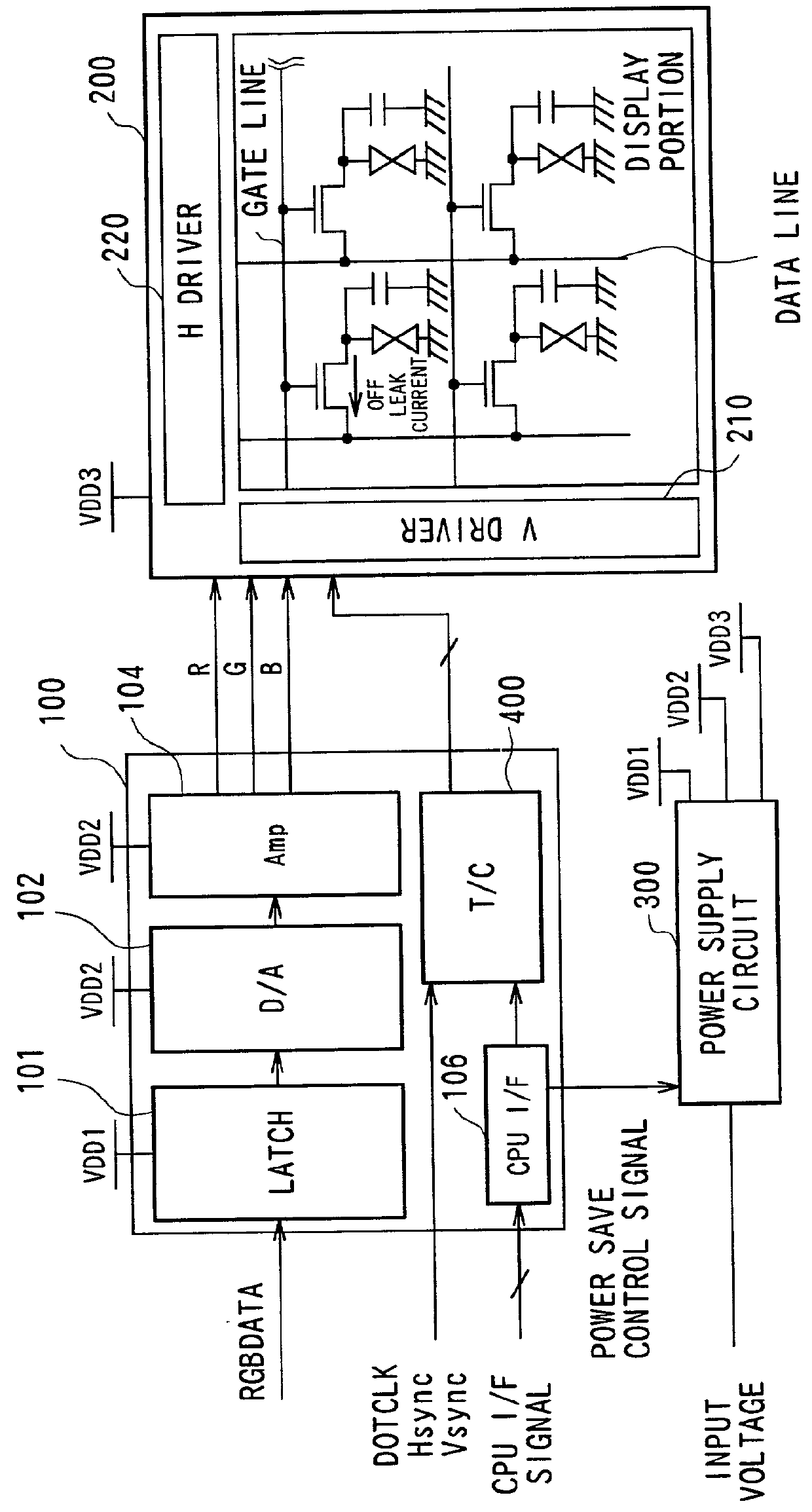
[0080] FIG. 1 schematically depicts the configuration of a display panel according to the present invention. This display panel corresponds to, for example, a flat display panel such as a Liquid Crystal Display (LCD) mounted on a mobile telephone. The display panel consists of a LCD panel 200 in which a liquid crystal is injected between a pair of substrates, a drive circuit 100 for driving the LCD panel 200, and a power source circuit (power supply circuit) 300 for supplying necessary power source voltages (e.g. VDD1, VDD2, VDD3) to the drive circuit 100 and to the LCD panel 200.

[0081] The LCD panel 200 is an active matrix-type LCD panel on respective pixels of which can be displayed an image. In the LCD panel 200, thin-film transistors acting as switching elements are arranged for respect...


PUM


Abstract

In the driving of a liquid crystal display panel with pixels in a matrix comprising n rows and m columns, when a partial display instruction is issued, respective rows in a display area (202) of s rows and m columns within the matrix are sequentially selected for one frame. Then, predetermined partial display data is written into the selected rows. Predetermined background data such as white display data is written into the background area (204) other than the partial display area (202). In the background area 204, either k rows and m columns or pixels of (the leading row ((s+1)-th row) of the background area, next to the final row in the partial display area) are selected during one frame for writing of the background display data, k rows and m columns are sequentially shifted each frame.

Description

[0001] 1. Field of the Invention[0002] The present invention relates to a method and circuit for driving a flat display device such as a liquid crystal display. The present invention also relates to a technique of generating a partial display on such a flat display device.[0003] 2. Description of Related Art[0004] Flat display devices, typified by liquid crystal displays, organic electroluminescence displays, and equivalents, are thin and lightweight and have low power consumption. These devices are preferable for portable devices such as mobile telephones, and have come to be used in a large number of portable devices.[0005] A matrix-type display device which can display an arbitrary pattern generated by a plurality of pixels arranged in a matrix form; a segment-type display device such as commonly used in timepieces, which can display a fixed pattern; and a hybrid display device comprising a combination of matrix and segment elements are known types of flat display devices.[0006] ...

Claims


Application Information

Patent Timeline
Patent Type & Authority Applications(United States)
IPC IPC(8): G09G3/36G09G5/02
CPCG09G3/3648G09G3/3677G09G3/3688G09G5/024G09G2310/0248G09G2310/04G09G2320/043G09G2330/021G09G3/36
Inventor TSUTSUI, YUSUKEKITAGAWA, MAKOTOKOBAYASHI, MITSUGUUEHARA, HISAOFUJIOKA, MAKOTO
Owner SANYO ELECTRIC CO LTD
Why Eureka
Try Eureka