Telecommunications antenna intended to cover a large terrestrial area

a technology for terrestrial areas and telecommunications antennas, applied in antennas, antenna adaptation in movable bodies, active radio relay systems, etc., can solve problems such as large number of components, and achieve the effect of reducing the number of low-noise amplifiers

Inactive Publication Date: 2002-01-17
ALCATEL LUCENT SAS
View PDF0 Cites 15 Cited by
  • Summary
  • Abstract
  • Description
  • Claims
  • Application Information

AI Technical Summary

Benefits of technology

[0012] The invention significantly reduces the number of low-noise amplifiers, phase-shifters and attenuators.
[0019] Controlling the phase-shifters in series with the low-noise amplifiers to correct or modify the beams is particularly simple in a receive antenna according to the invention.
[0021] To reduce the effect of an amplifier failure on the output signals, in one embodiment the low-noise amplifier which is associated with each output of the first Butler matrix includes a plurality (for example a pair) of amplifiers in parallel, for example interconnected by couplers. In this case, the degradation due to failure of only one of the two amplifiers of a pair is half or less than that if a single amplifier were associated with each output.
[0026] It is already known in the art to use a structure with two Butler matrices for send antennas in order to distribute the send power over all of the power amplifiers, but in these prior art antennas the beams are corrected or reconfigured in the manner described for receive antennas with reference to FIG. 2. Accordingly, for send antennas, the invention reduces the number of phase-shifters, and where applicable attenuators, and also simplifies their control. Moreover, for receive antennas, as indicated above, the invention reduces the number of low-noise amplifiers (compared to prior art receive antennas).

Problems solved by technology

A large number of components is a problem on a satellite because of their mass.
Also, a large number of phase-shifters 42 and attenuators 44 causes reliability problems.

Method used


Image

  • Telecommunications antenna intended to cover a large terrestrial area
  • Telecommunications antenna intended to cover a large terrestrial area
  • Telecommunications antenna intended to cover a large terrestrial area

Examples


Embodiment Construction

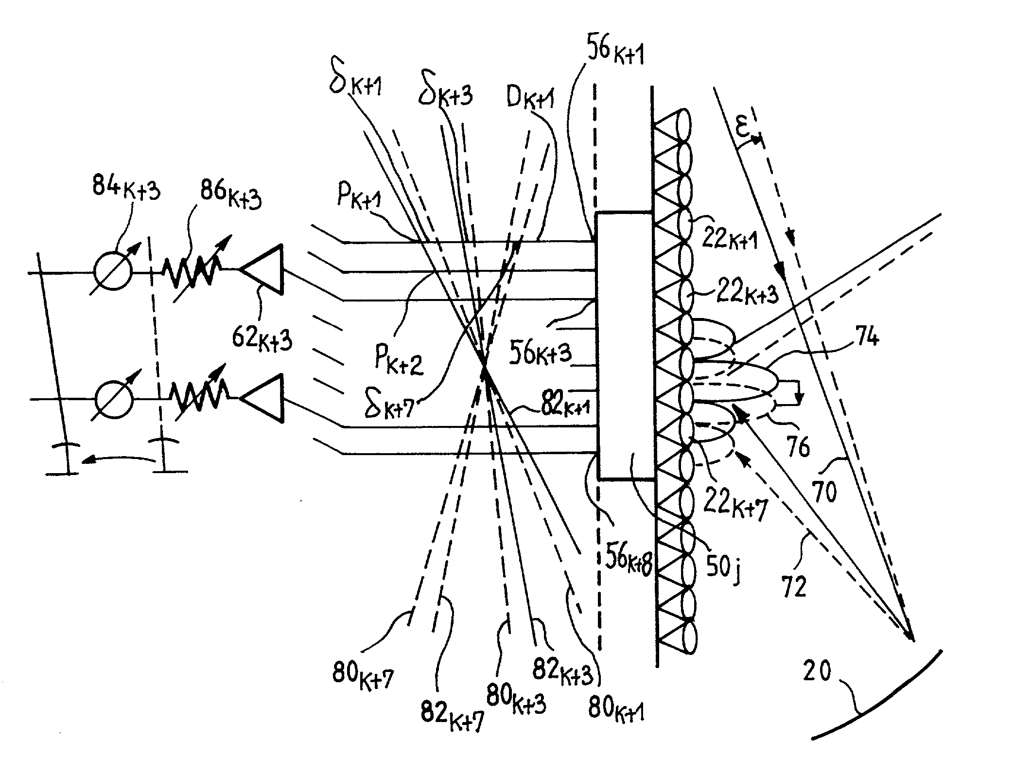
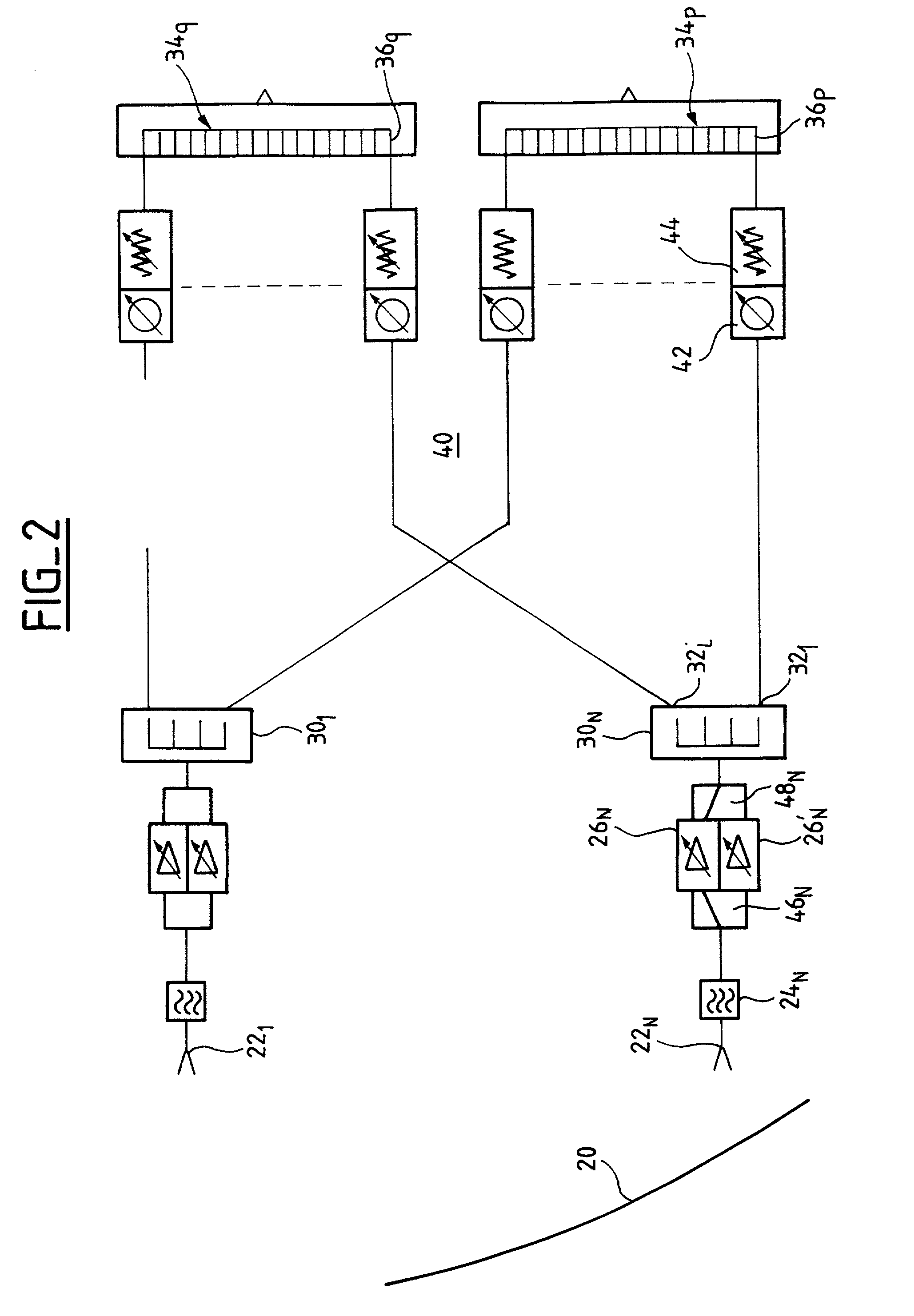
[0049] Like the antenna shown in FIG. 2, the receive antenna shown in FIG. 3 includes a reflector (not shown in FIG. 3) and a plurality of radiating elements 22.sub.1, . . . , 22.sub.N disposed in the vicinity of the focal area of the reflector.

[0050] In the FIG. 3 example, the receive antenna includes a plurality of Butler matrices 50.sub.1, . . . , 50.sub.j . . . , 50.sub.p. The matrices are all identical, with the same number of inputs and outputs.

[0051] Each input receives the signal from a radiating element. Thus the Butler matrix 50.sub.j has eight inputs 52.sub.1 to 52.sub.8 and the input 52.sub.1 receives the signal from the radiating element 22.sub.k+1. The input 52.sub.8 receives the signal from the radiating element 22.sub.k+8. In one embodiment, the radiating elements 22.sub.k+1 to 22.sub.k+8 are all assigned to one area, i.e. to one beam. However, as indicated above, some of these radiating elements also contribute to forming other beams for adjacent areas.

[0052] Each o...


PUM


Abstract

The invention relates to a receive (or send) antenna for a geosynchronous satellite of a telecommunications system intended to cover a territory divided into areas, the beam intended for each area being defined by a plurality of radiating elements, or sources, disposed in the vicinity of the focal plane of a reflector. The antenna includes at least one first matrix each input of which is connected to a radiating element and each output (or input) of which is connected to a corresponding input of an inverse Butler matrix by an amplifier and a phase-shifter. The phase-shifters move the areas or correct pointing errors.

Description

[0001] The invention relates to a telecommunications antenna which is installed on a geosynchronous satellite and is intended to relay communications over an extensive territory.[0002] A geosynchronous satellite which carries a send antenna and a receive antenna, each of which has a reflector associated a multiplicity of radiating elements or sources, is used to provide communications over an extensive territory, for example a territory the size of North America. In order to be able to re-use communications resources, in particular frequency sub-bands, the territory to be covered is divided into areas and the resources are assigned to the various areas so that when one area is assigned one resource adjacent areas are assigned different resources.[0003] Each area has a diameter of the order of several hundred kilometers, for example, and its extent is such that, to provide a high gain and sufficiently homogeneous radiation from the antenna in the area, it must be covered by a plurali...

Claims


Application Information

Patent Timeline
Patent Type & Authority Applications(United States)
IPC IPC(8): H01Q1/28H01Q3/26H01Q3/36H01Q3/40H01Q25/00H04B7/15
CPCH01Q3/2658H01Q3/40H01Q25/007H01Q25/008
Inventor CAILLE, GERARDCAILLOCE, YANN
Owner ALCATEL LUCENT SAS
Why Eureka
Try Eureka