Method and apparatus for reserving a place in line
- Summary
- Abstract
- Description
- Claims
- Application Information
AI Technical Summary
Problems solved by technology
Method used
Image

Examples
first embodiment
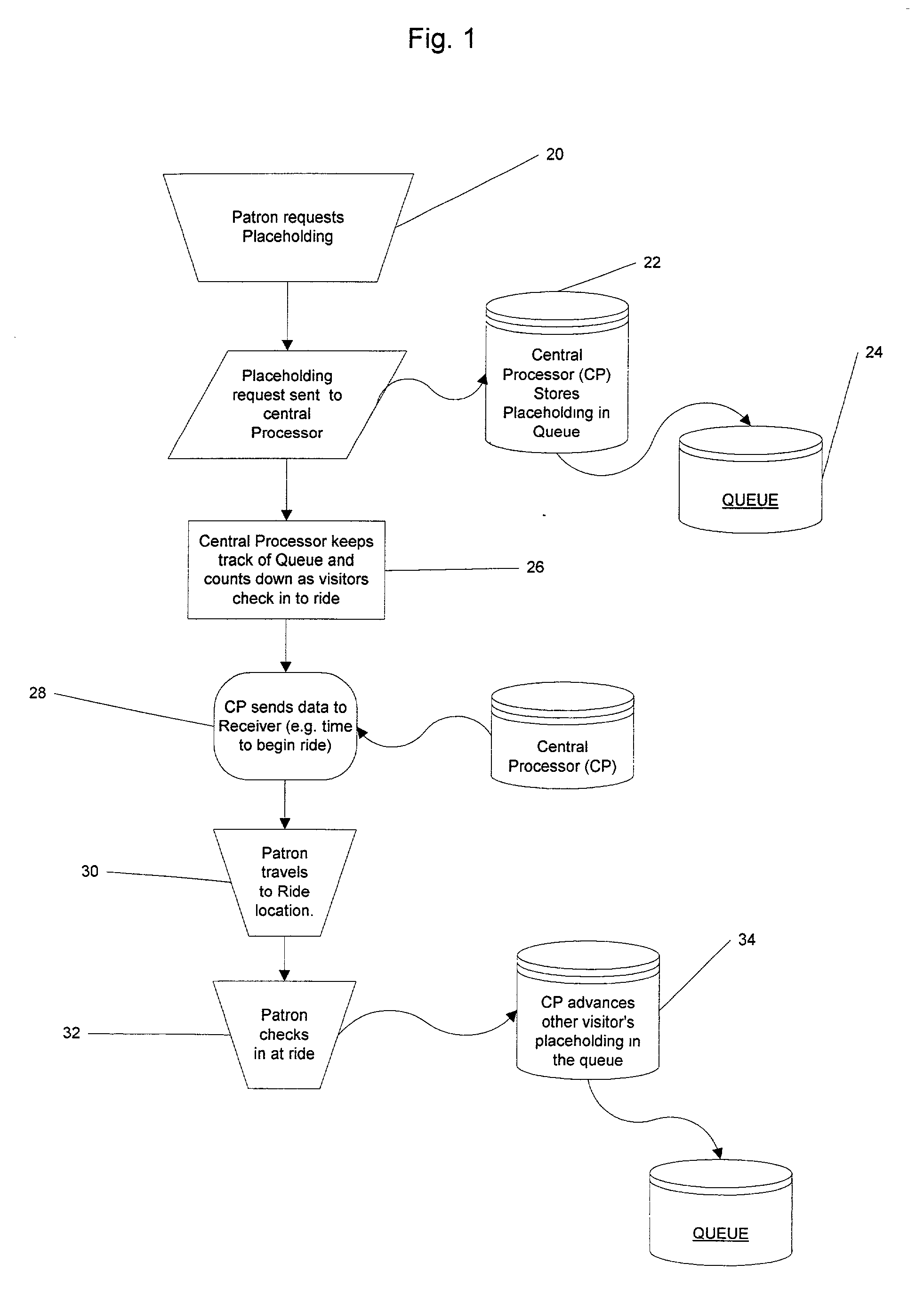
[0052] The basic operations of the present invention are as follows. As seen in FIG. 1, the user requests a place-holding on the queue and this is indicated at 20. The request can be made by a variety of potential input methods. Varieties of different methods are discussed below for exemplary purposes with the understanding that the basic principle is that the central processor receives a digital input for processing. The request is then sent to the central processor indicated at 22. The central processor then places the request on the queue 24. The queue is a dynamic data structure that keeps track of the number of requests and associated data therewith. The request itself contains the unique ID that is associated with the patron who made the request. Additional data fields can be associated therewith such as the time the request was made.
[0053] After the request has been made the patron can travel about the park freely. In the meantime the central processor is decrementing the que...
second embodiment
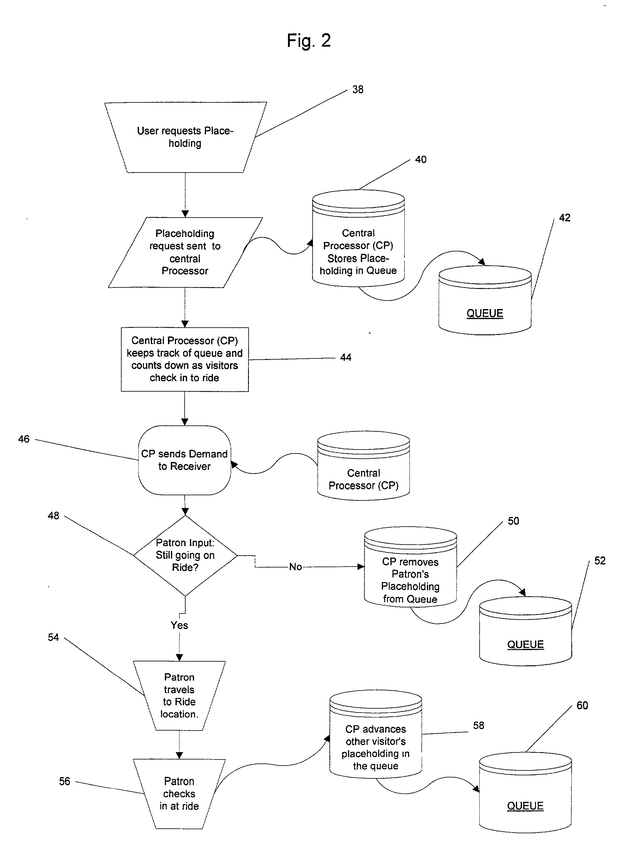
[0055] the present invention is shown in FIG. 2. In this embodiment the patron is given a choice as to whether she wants to go on the ride at her predetermined place-holding in the queue, at a lower priority position in the queue (a little bit later) or not all.
[0056] The first steps are similar to that of the first embodiment in FIG. 1 where the user requests a place-holding (again the methods of requesting a place-holding is discussed further infra) indicated at 38. This request is sent to the central processor 40, which places a place-holding identifying the user onto the queue 42. The central processor keeps a running count of the queue and decrements place-holdings as other patrons check-in to the ride when requested or miss the ride altogether (see 44 of FIG. 2). At a predetermined time interval, the central processor will send a demand to the specific patron indicated at step 46. As seen in FIG. 2, the demand is of a Boolean nature where the patron must decide whether or not ...
third embodiment
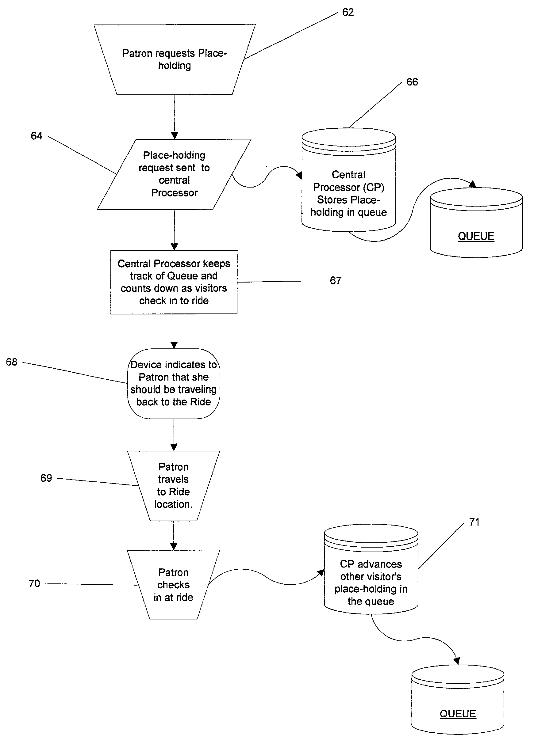
[0060] FIG. 3 shows a third embodiment where the receiver is replaced with only a timing device. In general, once the patron requests a place-holding on the queue this activates a countdown timer on the patron's timing device. After the central processor sets the timer, no further communication takes place between the central processor and the patron's device until the patron checks in to the ride at her designated time. This embodiment has a lower upfront cost for implementation since it does not require any long-range RF transmission between a transmitting center that is connected to the central processor and the devices carried by the patrons. As seen in FIG. 3, the patron makes a request at step 62. As with the previously mentioned embodiments this request can be executed by the patron walking through a sensing device such as an H-field interrogator that one commonly sees in a library, for example. Other methods of making a request could include running the countdown timer devic...
PUM
 Abstract
Description
Claims
Application Information
 - Generate Ideas
- Intellectual Property
- Life Sciences
- Materials
- Tech Scout
- Unparalleled Data Quality
- Higher Quality Content
- 60% Fewer Hallucinations
Browse by: Latest US Patents, China's latest patents, Technical Efficacy Thesaurus, Application Domain, Technology Topic, Popular Technical Reports.
© 2025 PatSnap. All rights reserved.Legal|Privacy policy|Modern Slavery Act Transparency Statement|Sitemap|About US| Contact US: help@patsnap.com