

Display equipment, display method, and storage medium storing a display control program using sub-pixels
a display control and subpixel technology, applied in the field of display equipment, can solve the problems of large system resources, difficult to achieve detailed display, and affecting the effect of artistic effect,
- Summary
- Abstract
- Description
- Claims
- Application Information
AI Technical Summary
Benefits of technology
Problems solved by technology
Method used
Image

Examples
first embodiment
[0101] (First Embodiment)
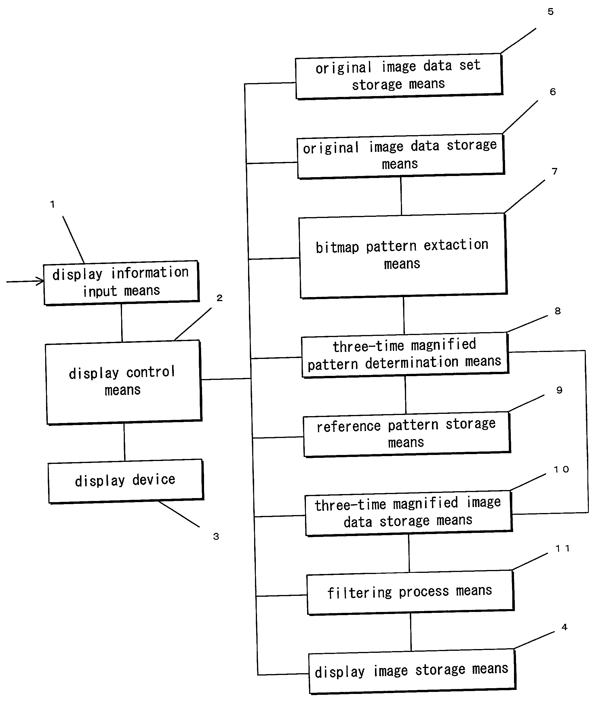
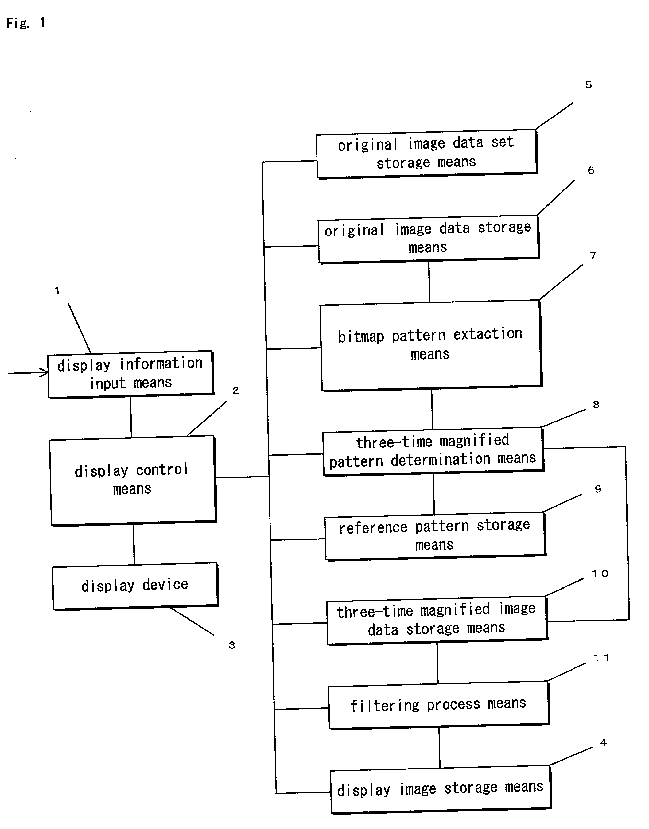
[0102] Referring to FIG. 1, a display information input means 1, of a first embodiment, receives display information. A display control means 2 controls the various elements of FIG. 1 to display a display image on a display device 3. The display is created from the display information stored in a display image storage means 4 (VRAM, etc.).
[0103] The display device 3 employs sets of three light-emitting elements, which respectively emit light of the three primary colors of R, G, and B. The three light-emitting elements of a set are aligned in a fixed order to form one pixel. A plurality of pixels thus formed are aligned in a first direction to form one line. A plurality of such lines are aligned in a second direction, which is orthogonal to the first direction, to form the display screen. To be more specific, the display device 3 is a color LCD or color plasma display, etc., including a suitable driver for driving the respective elements of the color LCD or c...
second embodiment
[0139] (Second Embodiment)
[0140] Referring now to FIG. 3, a second embodiment of the invention is similar to the first embodiment of FIG. 1, except that the three-times magnified pattern determination means 8 is replaced by a three-times magnified pattern logical operation means 12. Because most of the elements and operations of the embodiment in FIG. 3 are identical to corresponding elements in FIG. 1, only the differences are described. FIG. 3 is a block diagram of the display equipment of the second embodiment of this invention. Unlike the first embodiment, the three-times pattern determination rules are not stored but are determined by a logical operation process in the present embodiment.
[0141] Referring now to FIGS. 11(a)-(g), the logical operation performed by the three-times magnified pattern logical operation means 12 uses functions that make the conditional decisions shown in FIG. 11(b) onwards on the central target pixel (0, 0) and the adjacent pixels (total of 3.times.3 ...
third embodiment
[0159] (Third Embodiment)
[0160] The third embodiment of the invention, for achieving the second object, is now disclosed with reference to FIG. 12. An input means 21, which may be, for example, a keyboard or mouse, etc., accepts the input of character strings to be displayed, operation instructions, etc. A display control means 22 controls the various elements shown in FIG. 12 in accordance with the flowchart of FIG. 14. In particular, the display control means 22 allocates the sub-pixel image in a display image storage means 30 to the respective light-emitting elements of a display means 23 and thereby enables the display means 23 to perform display.
[0161] A character string storage means 24 stores the character string to be displayed. A font storage means 25 stores various font data, which may be vector fonts or raster fonts.
[0162] A format information storage means 26 stores the format information that is referenced in the process of formatting the respective characters of the ch...
PUM
 Abstract
Description
Claims
Application Information