Inkjet recording apparatus
a recording apparatus and inkjet technology, applied in the direction of printing, other printing apparatus, etc., can solve the problems of high ink sensitivity, long detection time of one-by-one nozzle detection technique, and long time required to implement detection of ink ejection, etc., and achieve the effect of high accuracy
- Summary
- Abstract
- Description
- Claims
- Application Information
AI Technical Summary
Benefits of technology
Problems solved by technology
Method used
Image

Examples
first embodiment
[0085] A: First Embodiment
[0086] B: Second Embodiment
[0087] C: Third Embodiment
[0088] D: Fourth Embodiment
[0089] E: Fifth Embodiment
[0090] A. First Embodiment
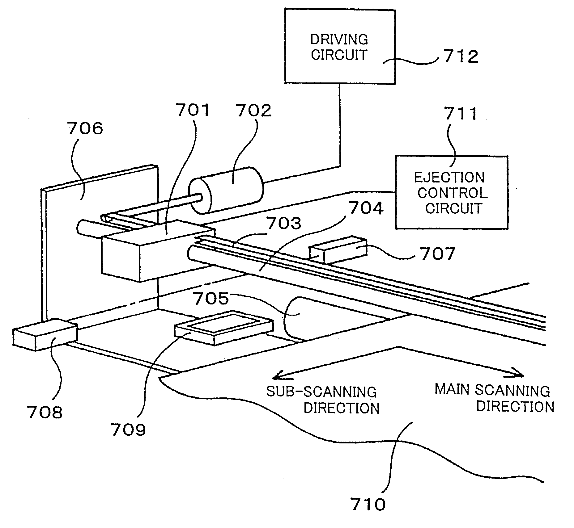
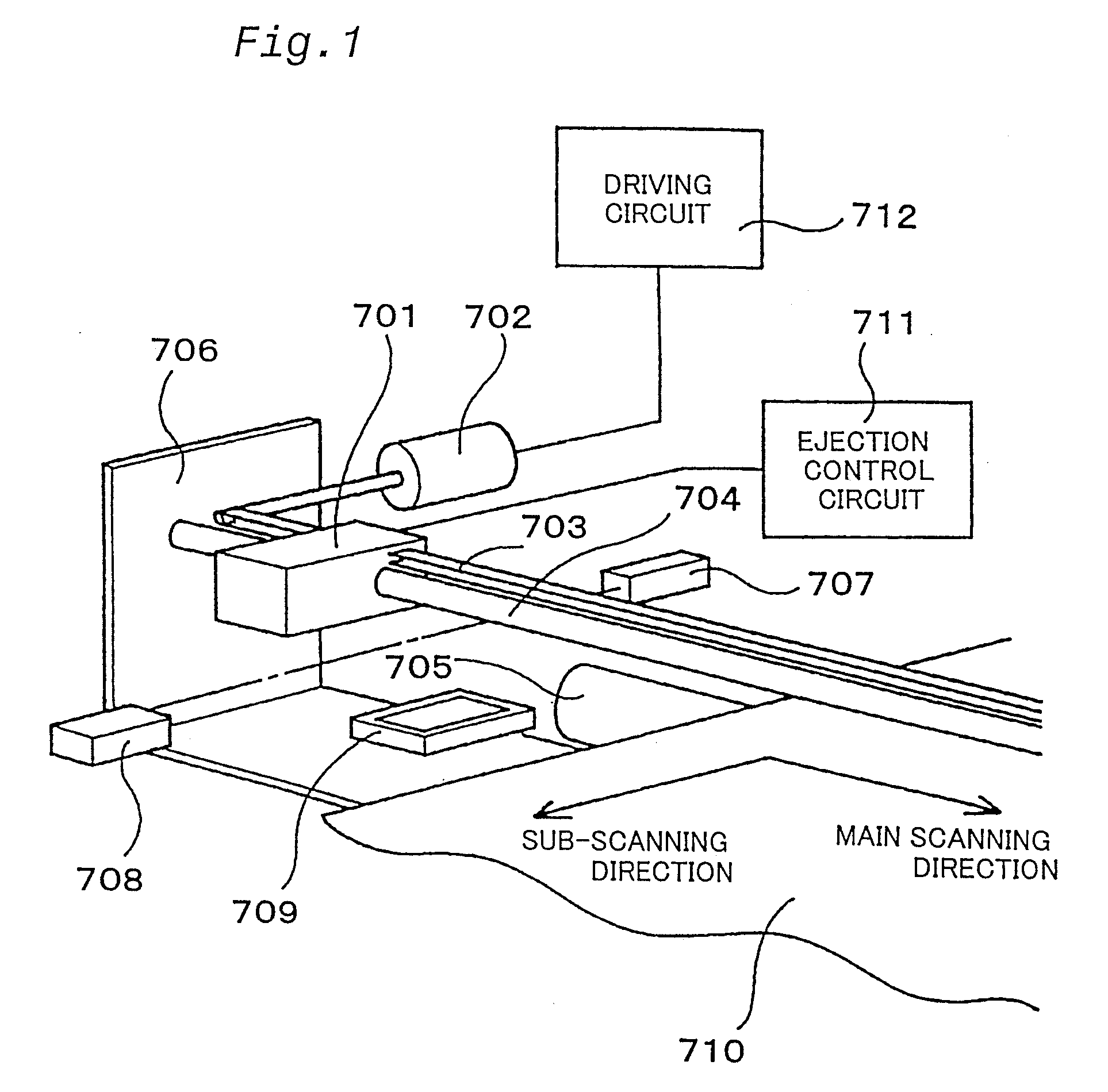
[0091] Fig. 1 illustrates the structure of one embodiment of the present invention. The structure has an ink jet print head 701 and print head shifting means 702 through 704 that shifts the ink jet print head 701 in a main scanning direction. More specifically the print head shifting means includes a motor 702, a garter belt 703 that connects with the motor 702 and the ink jet print head 701, and a guide roller 704. The structure further includes a platen roller 705 that functions as sheet feeder means, a guide frame 706, a light emitter 707 that functions as light emitting means, and a light receiver 708 that is disposed at a position facing the light emitter 707 and functions as light receiving means. In all the drawings, the one-dot chain line represents the pathway of a light flux emitted from the light emitter. The structu...
second embodiment
[0113] B. Second Embodiment
[0114] A second embodiment of the present invention is shown in Fig. 11. Fig. 11 illustrates the ink jet print head 701 having a plurality of nozzle arrays that are arranged at an interval LD. Figs. 12 and 13 show the states in which the ink jet print head 701 passes through the light flux 730.
[0115] At the position of Fig. 12, a nozzle #1 in a first array is detected. With a further shift of the ink jet print head 701 in the main scanning direction, a nozzle #6 in a second array is detected at the position of Fig. 13. The procedure of detecting the nozzles #6 through #1 in the first array is identical with the procedure discussed in the first embodiment. The procedure of detecting the nozzles #6 through #1 in the second array is also identical with the procedure discussed in the first embodiment and is carried out immediately after the detection in the first array.
[0116] When the ink jet print head 701 has the plurality of nozzle arrays, it is required to...
third embodiment
[0123] C. Third Embodiment
[0124] C-1. Structure of Apparatus
[0125] Fig. 14 is a perspective view schematically illustrating the structure of a main part of a color ink jet printer 20 in one embodiment according to the present invention. The printer 20 includes a sheet stacker 22, a sheet feed roller 24 driven by a non-illustrated step motor, a platen plate 26, a carriage 28, a step motor 30, a traction belt 32 driven by the step motor 30, and a pair of guide rails 34 for the carriage 28. A print head 36 with a large number of nozzles formed therein is mounted on the carriage 28.
[0126] A sheet of printing paper P is wound up from the sheet stacker 22 by means of the sheet feed roller 24 and fed on the surface of the platen plate 26 in the sub-scanning direction. The carriage 28 is dragged by means of the traction belt 32 driven by the step motor 30 to move in the main scanning direction along the pair of guide rails 34. The main scanning direction is perpendicular to the sub-scanning...
PUM
 Abstract
Description
Claims
Application Information
 - Generate Ideas
- Intellectual Property
- Life Sciences
- Materials
- Tech Scout
- Unparalleled Data Quality
- Higher Quality Content
- 60% Fewer Hallucinations
Browse by: Latest US Patents, China's latest patents, Technical Efficacy Thesaurus, Application Domain, Technology Topic, Popular Technical Reports.
© 2025 PatSnap. All rights reserved.Legal|Privacy policy|Modern Slavery Act Transparency Statement|Sitemap|About US| Contact US: help@patsnap.com