Recording apparatus and method

a recording apparatus and a technology of a recording device, applied in the field of recording apparatus and a method, can solve the problems of deterioration of nozzles and/or elements, ink jet head failure to eject, and ink jet head failur

Inactive Publication Date: 2002-02-21
CANON KK
View PDF3 Cites 42 Cited by
  • Summary
  • Abstract
  • Description
  • Claims
  • Application Information

AI Technical Summary

Problems solved by technology

However, an ink jet head sometimes suffers from a symptom called ejection failure.
There are many causes why an ink jet head fails to eject.
Some of the causes are foreign objects which entered a nozzle or nozzles of a recording head during the manufacturing of the head, and deterioration of nozzles and / or elements for ejecting ink, which occurs as usage time of a recording head accumulates.
In the cases of the latter causes, it is possible that ejection failure might unexpectedly occur while a recording apparatus is in use.
However, as the number of the nozzles arranged in a recording head is increased to increase recording speed as has been in recent years as described above, this problem becomes unignorable.
Manufacturing a recording head free of a defective nozzle, or a recording head which is not likely to unexpectedly suffer from ejection failure, increases manufacturing cost, resulting in increases in recording head cost.
Occurrence of ejection failure such as the one described above results in the formation of an image having a defect such as an unwanted white line.
However, when a recording head having a defective or failed nozzle (which hereinafter may be referred to as "bad nozzle") is used in conjunction with the so-called single pass recording method, it is next to impossible to record an image so that the portion of a recording medium correspondent to the defective or failed nozzle will be filled with the ink from a normally working nozzle in order to make the portion of the image correspondent to the bade nozzle turn out inconspicuous.
Further, even in the case of the so-called multiscan recording method, that is, a recording method in which a given portion of a recording medium is subjected to two or more scanning runs of a recording head, although it depends on the position of a bad nozzle, and / or the number of bad nozzles, it is sometimes rather difficult to compensate for a bad nozzle so that the image portion correspondent to the bad nozzle will turn out inconspicuous.

Method used


Image

  • Recording apparatus and method
  • Recording apparatus and method
  • Recording apparatus and method

Examples


embodiment 1

[0098] (Embodiment 1)

[0099]

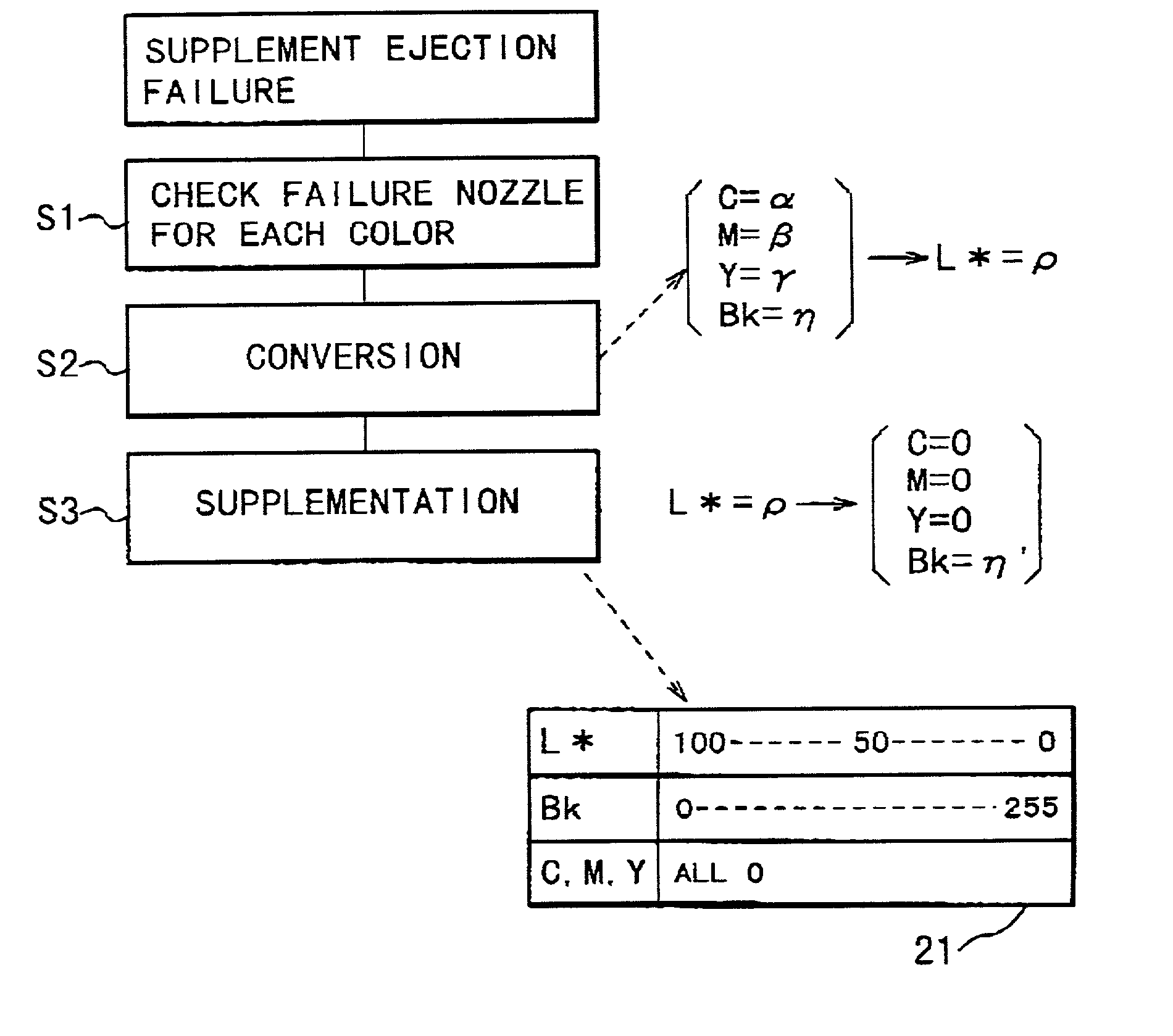
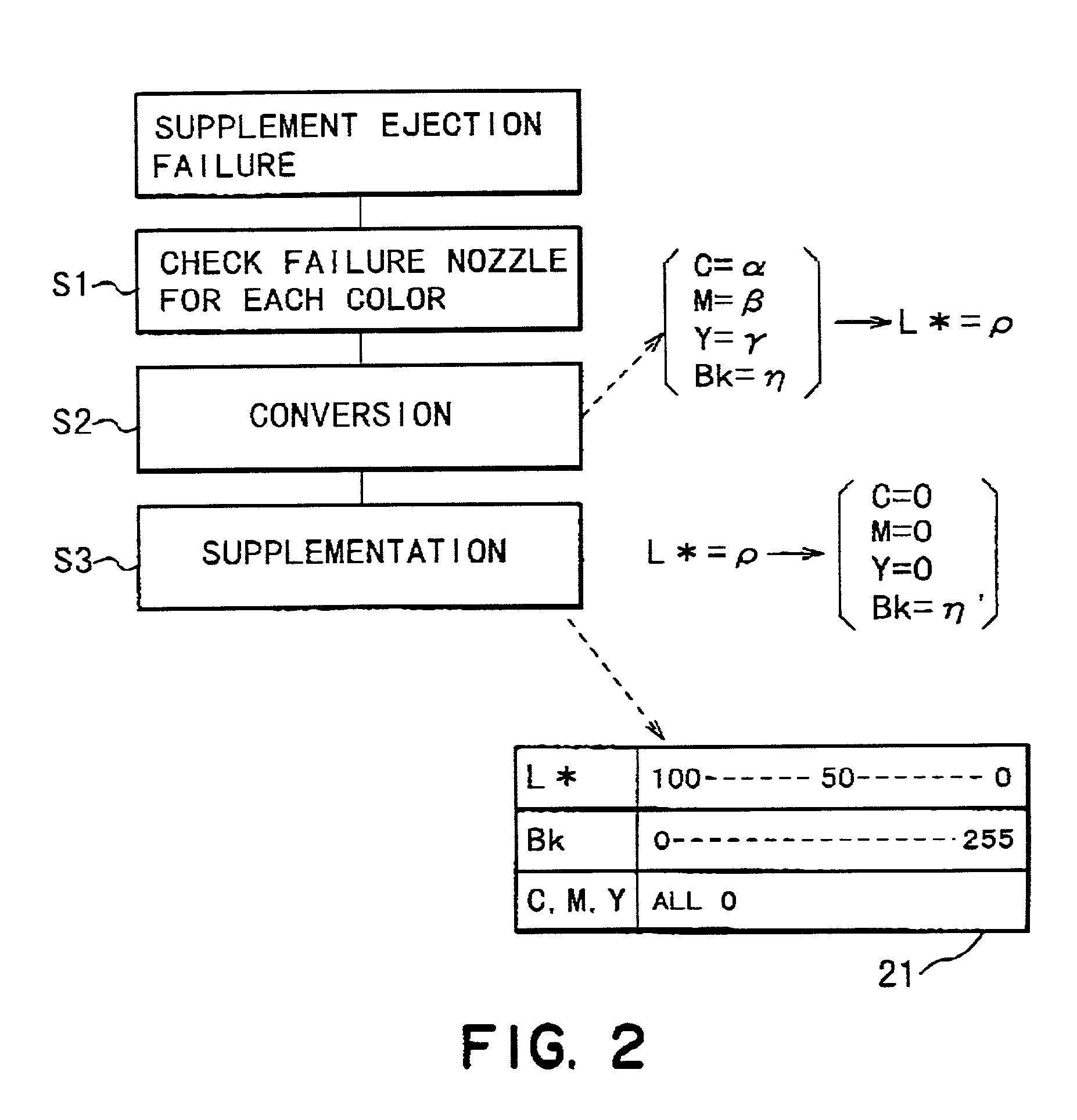
[0100] In this embodiment, the compensation for a failed nozzle for cyan ink and a failed nozzle for magenta ink is made with the use of a nozzle for black ink, based on the image data for the failed nozzle, in such a manner that the brightness of the portion of an image correspondent to the failed nozzle matches with the brightness of the surrounding portions of an image.

[0101] Hereinafter, the preferable embodiment of the present invention will be described in detail with reference to the appended drawings.

[0102] FIG. 13 is a sectional view of a color copying machine inclusive of an ink jet recording apparatus, in this embodiment, and shows the structure thereof.

[0103] This color copying machine comprises an image reading / processing portion (hereinafter, "reader portion 24"), and a printer portion 44. The reader portion 24 comprises: a CCD line sensor 5 equipped with three filters: R, G, and B color filters, a glass platen 1 for an original. An original...

embodiment 2

[0183] (Embodiment 2)

[0184]

[0185] In this embodiment, compensation for a bad nozzle, which is made to reduce nonuniformity in image density, is made by head shading. Nest, head shading will be more concretely described.

[0186] The system used in this embodiment for compensating for a bad nozzle is virtually the same as the one used in the first embodiment, except that in this embodiment, the data for filling the portion of an image correspondent to a bad nozzle, with the use of a nozzle different in ink color from the bad nozzle are not created.

[0187] Hereinafter, the data conversion process, that is, the process carried out by the combination of the a bad nozzle / nonuniform density detecting portion 93 and the data converting portion 94, will be described with respect to these two points.

[0188] Referring to FIG. 21, the process carried out by the bad nozzle / nonuniform density detecting portion 93 is basically the same as that in the first embodiment. Referring to FIG. 23, first, a t...

embodiment 3

[0207] (Embodiment 3)

[0208] This embodiment is a combination of the first embodiment in which compensation for a bad nozzle is made with the use of a nozzle different in ink color from the bad nozzle, and the second embodiment in which compensation for a bad nozzle is made by head shading. Thus, the same systems as those in the first and second embodiments can be used for this embodiment.

[0209] Hereinafter, the data conversion process in the printing operation in this embodiment will be described.

[0210] Referring to the block diagrams in FIGS. 21 and 26, the operation carried out in the failed nozzle / nonuniform density detecting portion 93 in this embodiment is the same as that in the second embodiment. In other words, the printing of a failed nozzle / nonuniform density detection test pattern, reading of the failed nozzle / nonuniform density detection test pattern, detection of bad nozzles, calculation of print density for each nozzle, and calculation of the density ratio data for eac...


PUM


Abstract

A recording apparatus for forming a color image on the recording material, includes a recording head having a plurality of recording elements; recording head driving means for driving the recording elements of the recording head in accordance with image data to form an image on the recording material; a plurality of supplementing means for effecting supplementations, in different manners, for supplementing defects in a recorded image resulting from a non-operating recording element of the recording elements; and control means for selectively operating the plurality of supplementing means depending on a record image to effect the supplementation.

Description

FIELD OF THE INVENTION AND RELATED ART[0001] The present invention relate to a recording apparatus which records with the use of a recording head having a plurality of recording element arranged in a predetermine pattern, and a recording method used with such a recording apparatus. In particular, the present invention relates to an ink jet recording apparatus which has a recording head having a plurality of nozzles arranged in a predetermined pattern, and records by ejecting ink from the plurality of nozzles.[0002] An ink jet recording apparatus which records on recording medium by ejecting ink from the nozzles arranged in the recording head has recently come to be used in a wide range of apparatus, for example, a printer, a facsimile machine, a copying machine, and the like. Also, in recent years, an ink jet recording apparatus has been remarkably improved in image quality, and therefore, its usage is dramatically growing in the field of a color printer capable of recording a color...

Claims


Application Information

Patent Timeline
Patent Type & Authority Applications(United States)
IPC IPC(8): B41J2/01B41J2/165B41J2/21
CPCB41J2/16579B41J2/2139
Inventor KOITABASHI, NORIBUMIYASHIMA, MASATAKASHIBATA, TSUYOSHI
Owner CANON KK
Why Eureka
Try Eureka