Double heat exchanger with condenser and radiator

a heat exchanger and condenser technology, applied in the field of double heat exchangers, can solve the problems of deteriorating performance of holding and fixing both heat exchangers, reducing the strength of side plates,

Inactive Publication Date: 2002-02-28
DENSO CORP
View PDF0 Cites 49 Cited by
  • Summary
  • Abstract
  • Description
  • Claims
  • Application Information

AI Technical Summary

Benefits of technology

[0007] According to an aspect of the present invention, in a double heat exchanger having a first core and a second core, a side plate is disposed at one side of the first and second cores to extend in a direction parallel with first and second tubes of the first and second cores for reinforcing the first and second cores, and the side plate is disposed to be connected to both first header tanks and both second header tanks at connection portions. The side plate has a flexible portion disposed to be flexible at least at one side of the connection portions, and a recess extending from one longitudinal end of the side plate until the flexible portion in a longitudinal direction of the side plate to separate the side plate at the one side of the connection portions. Accordingly, even when heat expansion amount is different in the first tubes of the first core and the second tubes of the second core, heat stress generated in the tubes can be absorbed by the deformation of the flexible portion. Further, because the recess extends from the one longitudinal end of the side plate until the flexible portion in the longitudinal direction of the side plate, the recess can be made shorter. Thus, in the double heat exchanger, the heat stress generated in the tubes can be reduced while it can prevent the strength of the side plate from being reducing.
[0008] According to an another aspect of the present invention, in a double heat exchanger with a first core and a second core, a side plate is disposed at one side of the first and second cores to extend in a direction parallel with first and second tubes of the first and second cores to be connected to both first header tanks and both second header tanks at connection portions, the side plate has a recess portion extending from one end in a direction crossing with the longitudinal direction of the side plate at least at one side of the connection portions, and the recess portion has a recess top part curved by a curvature radius larger than a predetermined dimension. Accordingly, even when a heat expansion amount in the second tubes is different from that in the first tubes, heat stress generated in the tubes can be absorbed by changing an opening area of the recess portion. Further, because the recess top part is curved by the curvature radius larger than the predetermined dimension, it can prevent the stress from being collected at the top end of recess portion. Therefore, it can prevent a crack from being caused at the top end of the recess portion. Thus, a durability of the side plate can be improved while the heat stress generated in the first and second tubes can be absorbed. Preferably, the curvature radius is equal to or larger than a thickness of the side plate. In this case, the durability of the side plate can be further improved.

Problems solved by technology

Accordingly, strength of the side plates is reduced, and a performance for holding and fixing both the heat exchangers is deteriorated.

Method used


Image

  • Double heat exchanger with condenser and radiator
  • Double heat exchanger with condenser and radiator
  • Double heat exchanger with condenser and radiator

Examples


first embodiment

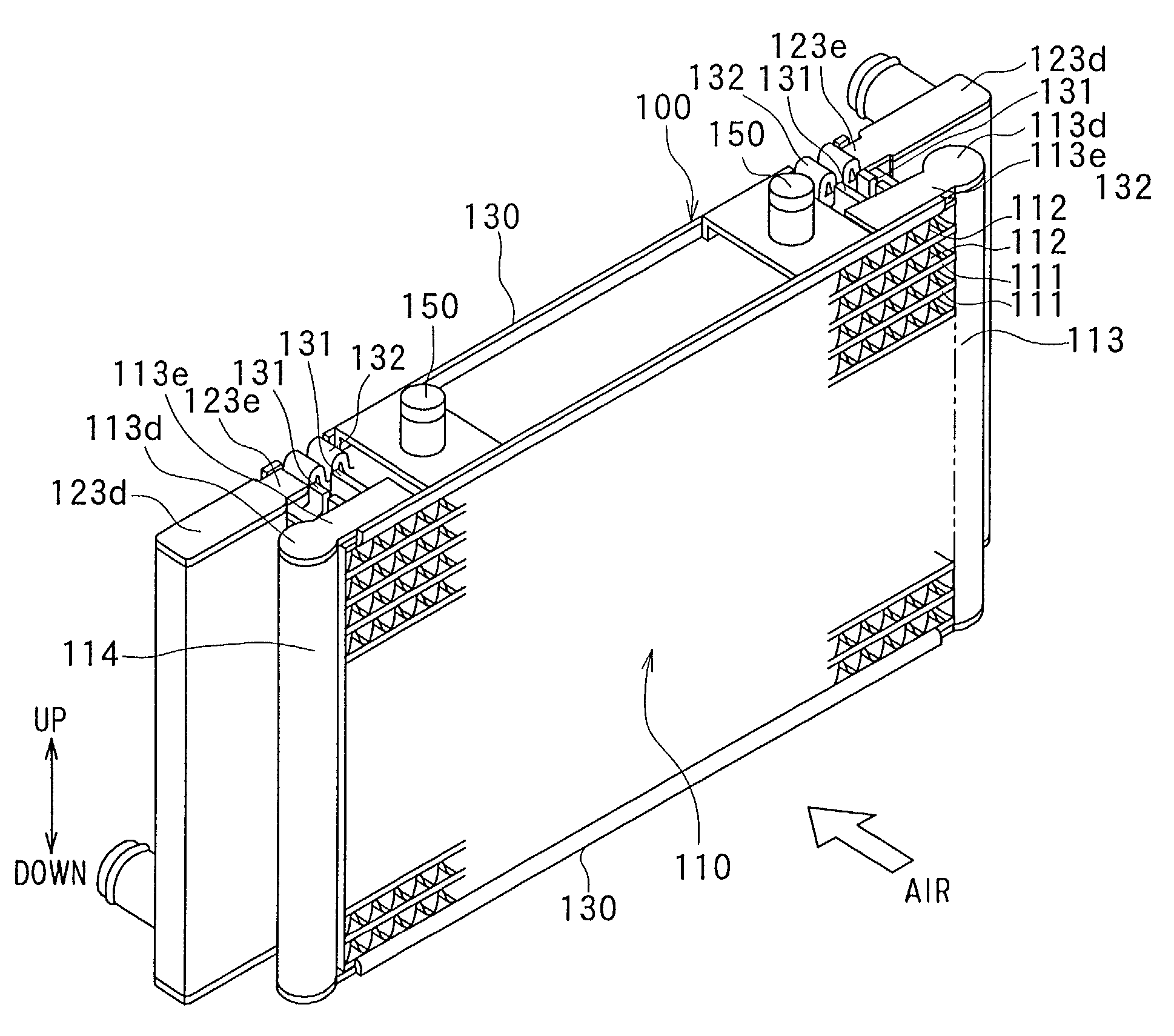
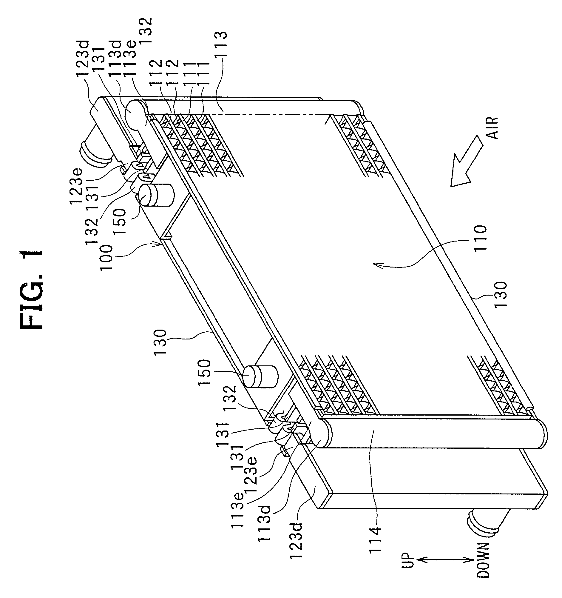
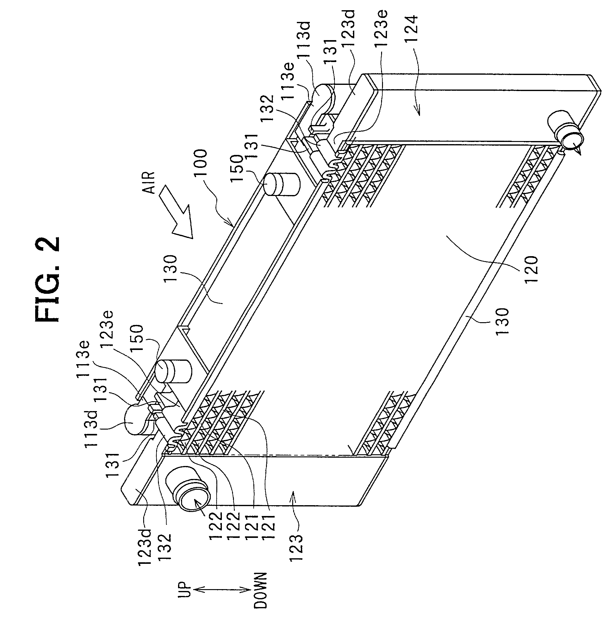
[0024] A first preferred embodiment of the present invention will be now described with reference to FIGS. 1-8B. In the first embodiment, the present invention is typically applied to a double heat exchanger 100 in which a condenser 110 of a vehicle refrigerant cycle and a radiator 120 for cooling engine-cooling water are integrated. The condenser 110 is disposed at an upstream air side of the radiator 120, as shown in FIGS. 1 and 2.

[0025] Refrigerant circulating in the refrigerant cycle is heat-exchanged with air in the condenser 110 to be cooled. The condenser 110 includes plural condenser tubes 111 (first tubes) made of an aluminum material, plural condenser fins 112 (first fins) each of which is made of an aluminum material and is disposed between adjacent condenser tubes 111 to facilitate a heat exchange between refrigerant and air, and condenser header tanks 113, 114 (first header tank) which are made of an aluminum material and are disposed at both longitudinal ends of each c...

second embodiment

[0044] A second preferred embodiment of the present invention will be now described with reference to FIG. 9. As shown in FIG. 9, in the second embodiment, a part of a side plate 130 is bent in a circular arc shape (dome shape) to form a flexible portions 132. Here, a curvature radius of the flexible portion 132 is made longer than a predetermined dimension, so that the stress generated in the flexible portion 132 can be made smaller, and it can prevent the strength of the side plate 130 from being reduced.

[0045] In the second embodiment, the other parts in the double heat exchanger are similar to those of the above-described first embodiment.

third embodiment

[0046] A third preferred embodiment of the present invention will be now described with reference to FIGS. 10A and 10B. In the third embodiment, as shown in FIGS. 10A and 10B, a flexible portion 132 is constructed by a bent portion 132b, and a recess portion recessed toward a curvature radial center is provided at a top portion of the bent portion 132b to form a reinforcement portion 132c. By providing the reinforcement portion 132c, a bending strength of the bent portion 132b of the flexible portion 132 can be increased.

[0047] In the third embodiment, the reinforcement portion 132c is provided in the flexible portion 132, so that the bending strength of the bent portion 132b can be increased in a range where the heat stress generated in the tubes 111, 121 can be absorbed by the flexible portion 132.


PUM


Abstract

In a double heat exchanger with a condenser and a radiator, a flexible portion formed into a wave shape to be flexible is provided in a side plate at least at one side of connection portions of the side plate, connected to condenser header tanks and radiator header tanks. Further, a slit is provided to be recessed from one longitudinal end of the side plate to the flexible portion. Accordingly, a heat stress generated in condenser tubes and radiator tubes can be absorbed by the flexible portion even when a length of the slit is made shorter.

Description

[0001] This application is related to and claims priority from Japanese Patent Applications No. 2000-261094 filed on Aug. 30, 2000, and No. 2000-365510 filed on Nov. 30, 2000, the contents of which are hereby incorporated by reference.[0002] 1. Field of the Invention[0003] The present invention relates to a double heat exchanger having several heat-exchanging portions such as a condenser and a radiator, in which different fluids having different temperatures flow, respectively.[0004] 2. Description of Related Art[0005] In a conventional double heat exchanger described in JP-A-8-178556, a first heat exchanger and a second heat exchanger are connected by side plates to be integrated with each other. Further, for reducing heat stress generated in tubes of both the heat exchangers, a recess extending from one longitudinal end toward the other longitudinal end of the side plate is provided. However, in this double heat exchanger, the recess extending in the longitudinal direction of the ...

Claims


Application Information

Patent Timeline
Patent Type & Authority Applications(United States)
IPC IPC(8): F28D1/04F28D1/053F28F1/02F28F9/00F28D1/00F28F9/02
CPCF28D1/0435F28D1/05383F28D2021/0084F28D2021/0094F28F1/022F28F9/001F28F9/0202F28F2215/02F28F2265/26F28F2009/004F28D1/00
Inventor UCHIKAWA, AKIRASUZUKI, SHINOBUMUTO, SATOMI
Owner DENSO CORP
Why Eureka
Try Eureka