Refrigeration systems

a technology of refrigeration system and charging system, which is applied in the direction of refrigeration components, fluid circulation arrangement, lighting and heating apparatus, etc., can solve the problems of inhibiting the operation of the evaporator, and achieve the effect of simplifying the charge system, avoiding the risk of damage to the goods stored, and ensuring the overall efficiency

Inactive Publication Date: 2002-03-07
NBS CRYO RES
View PDF0 Cites 5 Cited by
  • Summary
  • Abstract
  • Description
  • Claims
  • Application Information

AI Technical Summary

Benefits of technology

0016] It is normal for a conventional refrigeration system to include some form of control means, even if it is as simple as a thermostatic switch linked to the power supply. For reasons of simplicity and overall efficiency, the controller may be integrated in, or part of, an overall system controller.
0017] In addition to the advantages discussed above, the present invention offers at least two further advantages. Firstly if the heater should fail, the system can still continued to operate as an existing system thereby not increasing the risk of damage to the goods stored in a freezer using such a refrigeration system. In effect it is fail-safe. Secondly, use of the present invention simplifies the task of charging the system with refrigerant during manufacture. In existing systems, the amount of refrigerant introduced into the system has to be carefully controlled. Too little refrigerant causes poor performance, but if too much is contained, not only can performance suffer, but more importantly refrigerant condensing during the off-time can overflow the condenser and flood the compressor. In systems according to the present invention larger capacity accumulators may be used without sacrificing performance, as would be the case in existing systems. Therefore, a greater degree of variation in the amount of refrigerant introduced can be tolerated and the process of manufacture simplified.

Problems solved by technology

If the accumulator were to be heated continuously the pressure would remain high, thus inhibiting the operation of the evaporator.

Method used


Image

  • Refrigeration systems
  • Refrigeration systems

Examples


Embodiment Construction

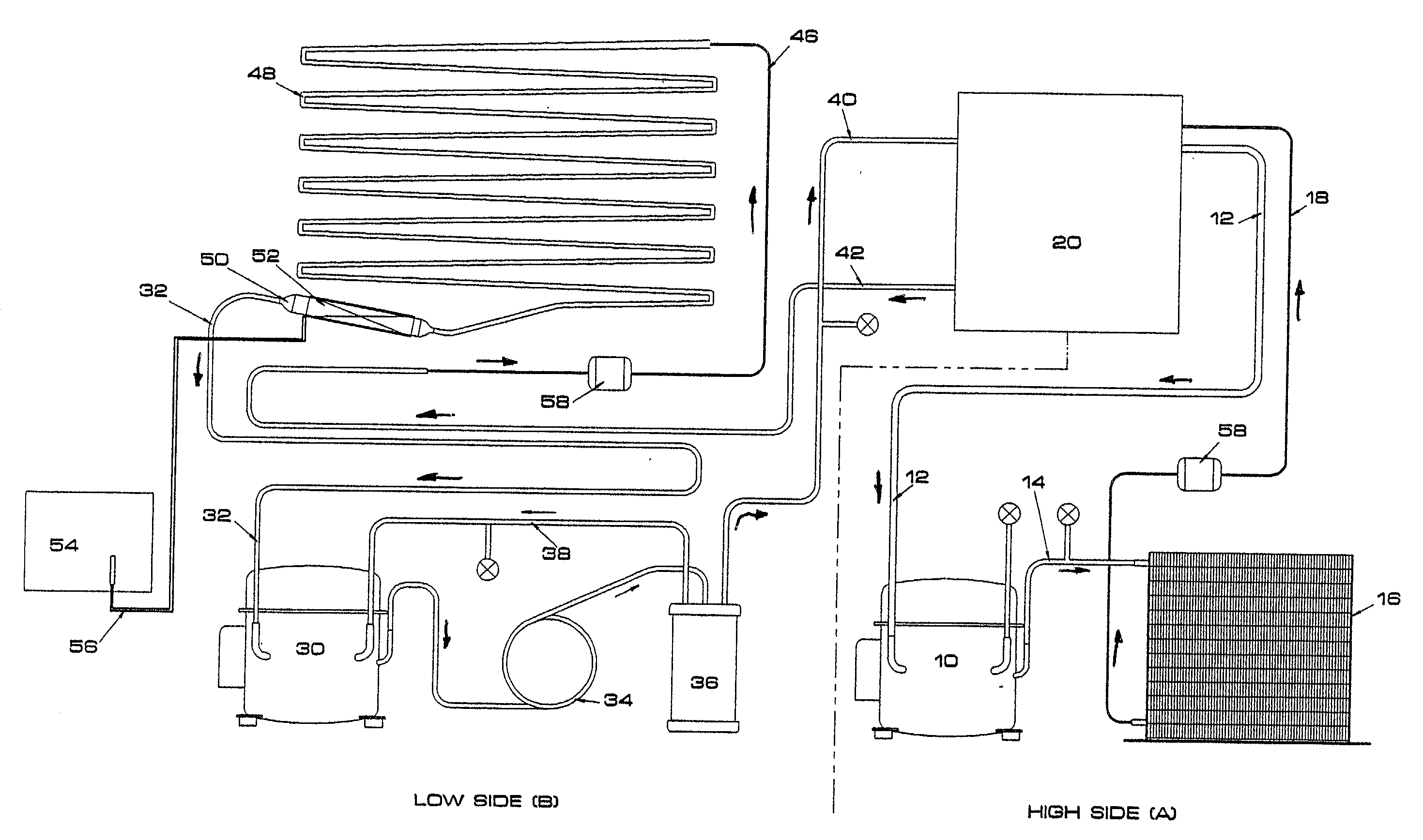
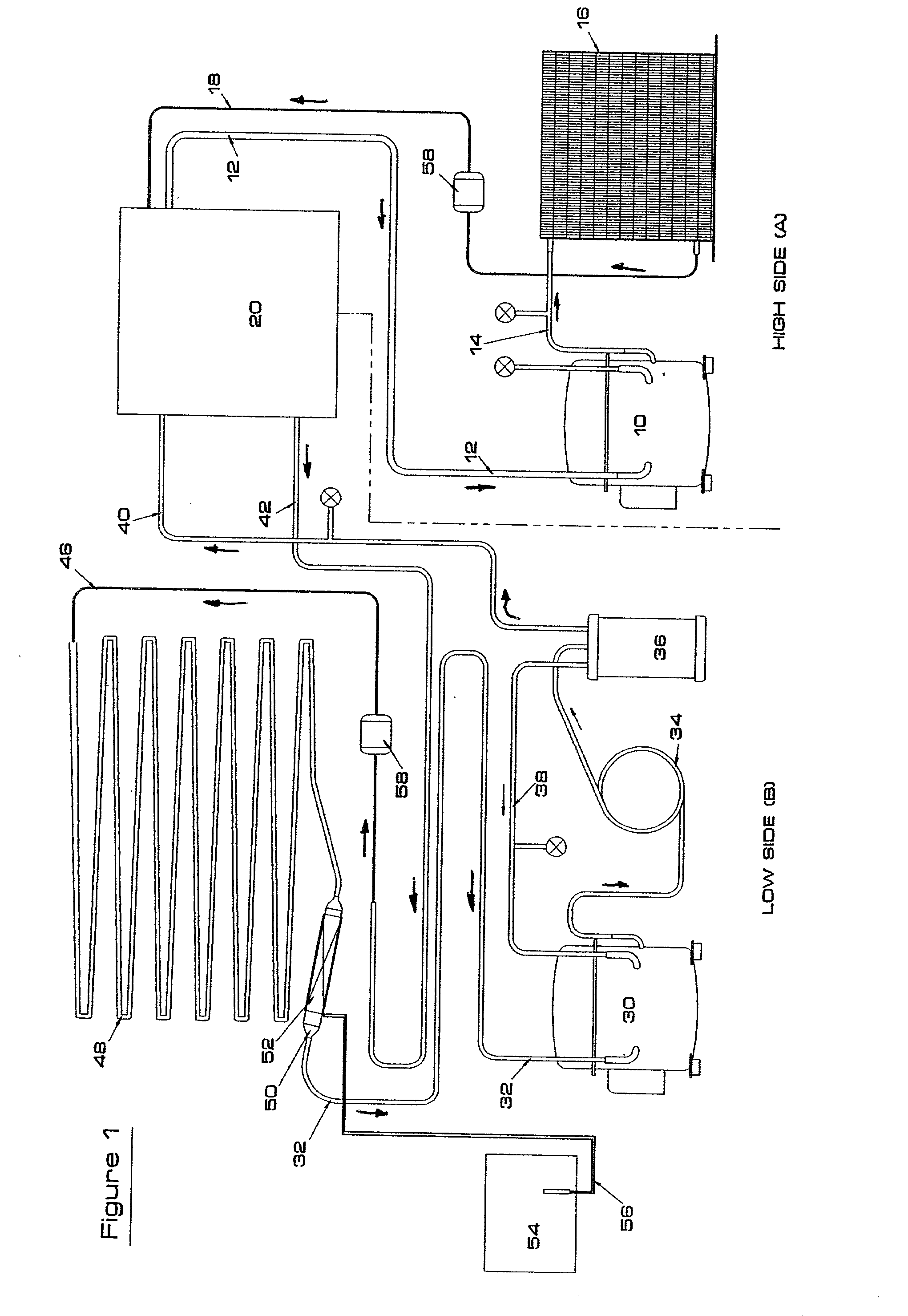
[0021] The refrigeration system shown in FIG. 1 has two discrete cycles; one generally termed the high-side (labelled A), and the other generally termed the low-side (labelled B). During periods of on-time in normal operation, the low-side draws heat from the area to be cooled, and the high-side is adapted to cool the refrigerant of the low-side and dissipate that heat to the external environment. Separate refrigerants flow around the two cycles and whilst they thermally interact they do not come into direct contact. The types of refrigerant used are well know in the prior art so will not be discussed in detail. In FIG. 1 the direction of flow is indicated by arrows.

[0022] The high-side cycle comprises a compressor 10 which receives gaseous refrigerant from a return pipe 12. The compressor pressurises the gaseous refrigerant and pumps it out through a discharge pipe 14 into the condenser 16. In the condenser, heat energy is dissipated from the condensing refrigerant to the external ...


PUM


Abstract

A refrigeration system which comprises a compressor, an evaporator to which liquid refrigerant compressed by the compressor is supplied through a flow restrictor, and return means which direct refrigerant expanded in the evaporator back to the compressor. The return means include an accumulator in which liquid refrigerant leaving said evaporator may collect, and heating means either integral with or attached to the accumulator. The heating means are adapted to supply heat energy to the liquid refrigerant collected by said accumulator in order to promote its evaporation, thereby increasing the overall efficiency of the refrigeration system. The heating. means may be controlled by a microprocessor.

Description

[0001] The present invention relates to refrigeration systems, and particularly (but not exclusively) to refrigeration systems for ultra-low temperature storage compartments.BACKGROUND OF INVENTION[0002] The operation of conventional low temperature refrigeration systems is well known in the art, so will not be described in detail here. However to appreciate the benefits provided by the present invention it is necessary briefly to explain how such conventional systems work.[0003] A basic refrigeration system comprises a compressor which compresses gaseous refrigerant and supplies it to a heat exchanger where the refrigerant is condensed to a liquid, giving out heat energy. This liquid refrigerant then passes through a flow restrictor into an evaporator whereat the low pressure and the expansion of the refrigerant causes the refrigerant to vaporise thereby absorbing heat. The gaseous refrigerant then passes out of the evaporator back to the compressor to begin the cycle again. An acc...

Claims


Application Information

Patent Timeline
Patent Type & Authority Applications(United States)
IPC IPC(8): F25B7/00F25B43/00
CPCF25B7/00F25B43/006F25B2400/01F25B2500/26
Inventor MINISTER, DAVID J.
Owner NBS CRYO RES
Why Eureka
Try Eureka