Controllable muffler system for internal combustion engine
Inactive Publication Date: 2002-03-21
CALSONIC KANSEI CORP +1
View PDF2 Cites 51 Cited by
Summary
Abstract
Description
Claims
Application Information
AI Technical Summary
This helps you quickly interpret patents by identifying the three key elements:
Problems solved by technology
Method used
Benefits of technology
Problems solved by technology
However, increase in cost can not be avoided because of employment of the control valves 103 and 106 which are actuated by complicated electronic control systems.
However, even the system of FIG. 10 tends to fail to exhibit a satisfied performance because of the nature of the exhaust pressure sensible valve 108.
In particular, adjustment of the valve 108 for obtaining a desired muffling performance is difficult.
Method used
Image
Click on the blue label to locate the original text in one second.
Reading with bidirectional positioning of images and text.
Examples
first embodiment
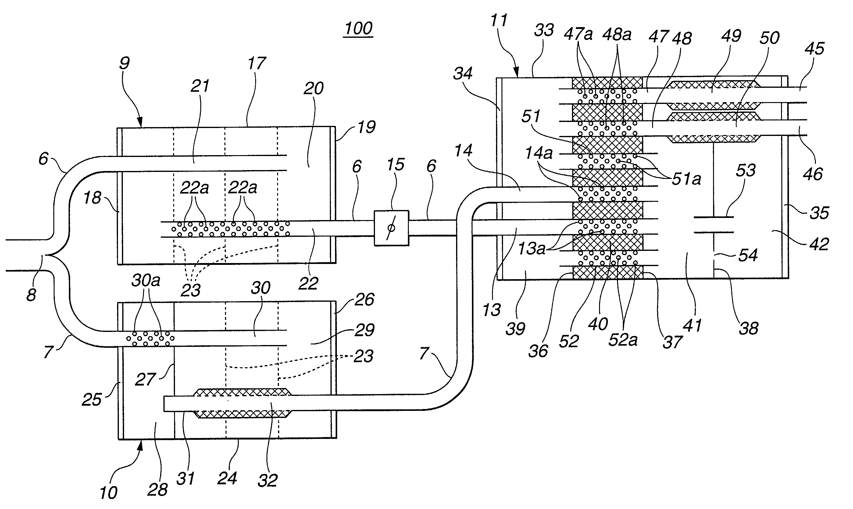
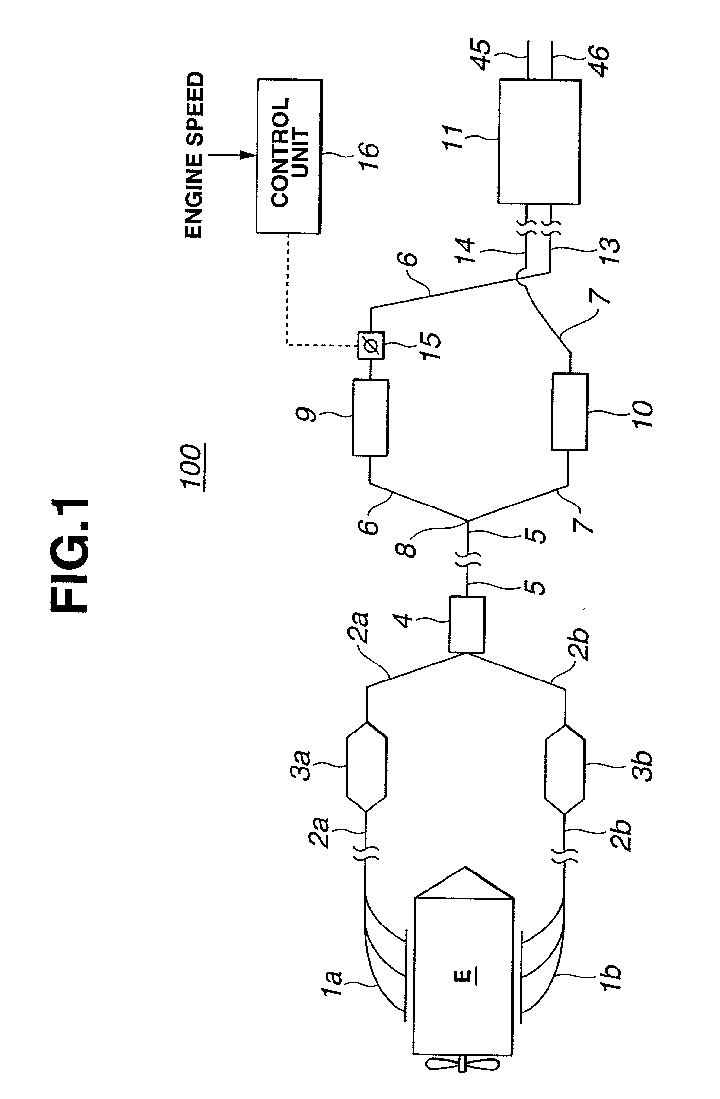
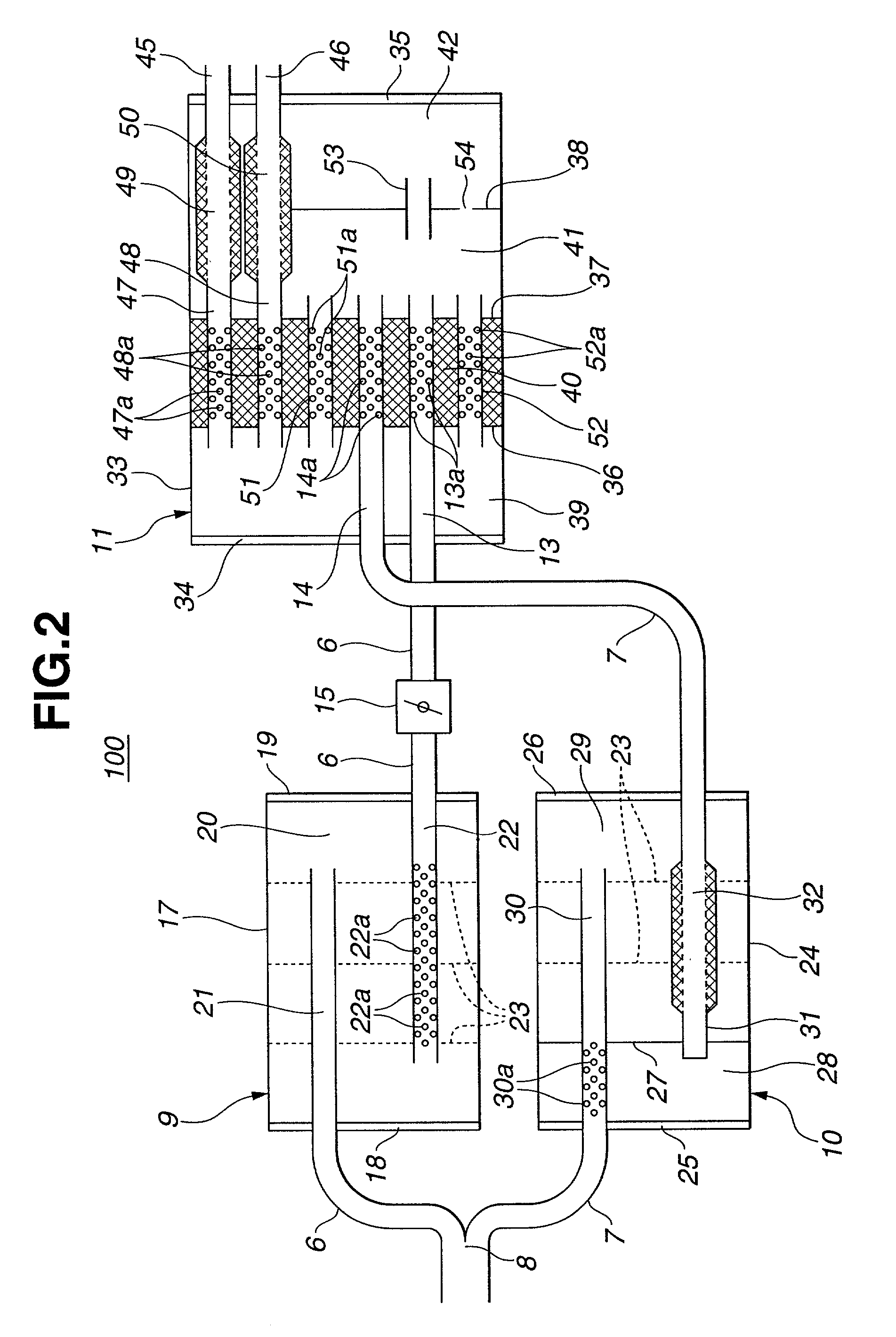
[0027] Referring to FIGS. 1 and 2, particularly FIG. 1, there is shown a controllable muffler system 100 which is the present invention.
[0028] In the drawing, denoted by reference "E" is a V-type internal combustion engine having two cylinder banks. As shown, from the two cylinder banks of the engine "E", there extend respective exhaust systems each generally comprising an exhaust manifold 1a or 1b which directly extends from the cylinder bank, a front tube 2a or 2b which extends from the exhaust manifold 1a or 1b and a catalytic converter 3a or 3b which is disposed on the front tube 2a or 2b. This system is called "dual exhaust system" and brings about a high engine performance because of a satisfied lowering of exhaust interference.
[0029] As shown, downstream ends of the front tubes 2a and 2b are united and led to an inlet of a front muffler 4. From an outlet of the front muffler 4, there extends a rear tube 5. The rear tube 5 has a branched rear end 8 from which two tubes 6 and 7...
second embodiment
[0065] Referring to FIG. 3, there is shown a controllable muffler system 200 which is the present invention.
[0066] That is, in the second embodiment 200, there is no means that corresponds to the first center muffler 9 used in the first embodiment 100.
[0067] Thus, when the butterfly valve 15 is closed, the upstream and downstream portions of the tube 6 with respect to the butterfly valve 15 can serves as the above-mentioned side branches thereby to effectively dampen the noises having specified frequencies. While, when the butterfly valve 15 is opened, the tube 6 can serve as a bypass passage for the center muffler 10 thereby to permitting the engine "E" to produce a higher output power.
[0068] Due to removal of the first center muffler 9, the freedom in positioning the butterfly valve 15 is improved thereby to much more effectively dampen the low frequency components of noises of the exhaust gas. Furthermore, due to removal of the muffler 9, the entire arrangement of the system 200 ...
third embodiment
[0069] Referring to FIG. 4, there is shown a controllable muffler system 300 which is the present invention.
[0070] In the third embodiment 300, the butterfly valve 15 is mounted on the tube upstream of the first center muffler 9.
[0071] That is, similar to the above-mentioned second embodiment 200, when the butterfly valve 15 is closed, the upstream and downstream portions of the tube 6 with respect to the butterfly valve 15 can serve as the above-mentioned side branches thereby to effectively dampen the noises having specified frequencies. In this third embodiment 300, substantially same advantages as those of the first embodiment 100 are obtained. In addition, due to position change of butterfly valve 15 relative to the first center muffler 9, the frequency of the noise effectively damped by the system 300 is changed.
PUM
Abstract
A controllable mufflersystem is sued for use with an engine that produces a power by burning fuel. The system comprises a first passage section extending from the engine for having an exhaust gas of the engine flow therethrough. The first passage section has a catalytic converter mounted thereon. The system further comprises a dual passage section including second and third passage sections which extend separately from an end of the first passage section. The second passage has a control valve for controlling the flow rate of the exhaust gas flowing therethrough. The system further comprises a fourth passage section extending from respective ends of the second and third passage sections to the open air. The fourth passage section has a rear muffler mounted thereon. The system further comprises a control unit which controls the control valve of the second passage section in accordance with an operation condition of the engine.
Description
[0001] 1. Field of the Invention[0002] The present invention relates in general to muffler systems of an automotive engines, and more particularly to the muffler systems of a controllable type that can control its sound muffling or dampening performance in accordance with engine speed or the like.[0003] 2. Description of Related Art[0004] In order to clarify the task of the present invention, some known controllable muffler systems of the above-mentioned type will be briefly described with reference to the accompanying drawings.[0005] In FIG. 8, there is shown one muffler system that is described in Japanese Patent First Provisional Publication 4-72408. The system of this publication generally comprises a chamber body 100A, an inlet pipe (no numeral) led into the chamber body 100A and two outlet pipes 101 and 102 extending to the outside from the interior of the chamber body 100A. The outlet pipe 101 is equipped with a control valve 103 that is controlled in accordance with an opera...
Claims
Application Information
Patent Timeline
Application Date:The date an application was filed.
Publication Date:The date a patent or application was officially published.
First Publication Date:The earliest publication date of a patent with the same application number.
Issue Date:Publication date of the patent grant document.
PCT Entry Date:The Entry date of PCT National Phase.
Estimated Expiry Date:The statutory expiry date of a patent right according to the Patent Law, and it is the longest term of protection that the patent right can achieve without the termination of the patent right due to other reasons(Term extension factor has been taken into account ).
Invalid Date:Actual expiry date is based on effective date or publication date of legal transaction data of invalid patent.

