Quantitative suction tip and quantitative suction apparatus

a quantitative suction and tip technology, applied in the direction of analytical using chemical indicators, instruments, laboratory glassware, etc., can solve the problems of reducing suction accuracy, reducing suction accuracy, and reducing suction accuracy, so as to achieve accurate quantitative drawing, improve control, and achieve satisfactory suction accuracy

Inactive Publication Date: 2002-03-28
FUJIFILM HLDG CORP
View PDF30 Cites 41 Cited by
  • Summary
  • Abstract
  • Description
  • Claims
  • Application Information

AI Technical Summary

Benefits of technology

[0008] It is plausible to reduce the influence of the wettability by increasing the water repellency of the tip surfaces. However, there still remain other unknown values including the surface tension and viscosity of the drawn liquid that cannot be dealt with, thereby causing an error in the quantity drawn and lowering the accuracy in the measurement and / or analysis, for example.
[0009] Accordingly, it is an object of the present invention to provide a quantitative suction tip for allowing a predetermined quantity of a liquid to be accurately drawn without being influenced by e.g. the surface tension and viscosity of the drawn liquid and the wettability of the inside walls of the tip. It is another object of the invention to provide a quantitative suction apparatus using such tip.
[0014] By thus employing the quantitative suction tip comprising the fixed volume chamber of a predetermined volume and the through hole with a different cross-sectional area than that of the fixed volume chamber, the drawing can be stopped on the basis of a pressure change indicating that the liquid has reached the though hole. Thus, a volume of the liquid filling the fixed volume chamber can be accurately quantitatively drawn, thereby ensuring a satisfactory suction accuracy. Accordingly, a predetermined quantity of the liquid can be drawn without being affected by e.g. the surface tension and viscosity of the liquid to be drawn and the wettability of the inside walls of the tip. Further, when the quantity drawn is to be changed, simply the volume of the fixed volume chamber may be changed without changing the suction quantity by the suction pump, so that better control can be obtained.

Problems solved by technology

However, when such a tip is used during the suction of a liquid, it is difficult to accurately draw and retain a predetermined quantity of the liquid within the tip by the control of the negative pressure on the suction pump side.
As a result, the quantity of the liquid that is actually drawn into the tip becomes less than the predetermined quantity even if the spatial volume of the suction pump is varied in proportion to the quantity of the liquid desired to be drawn, resulting in a reduced suction accuracy.
However, there still remain other unknown values including the surface tension and viscosity of the drawn liquid that cannot be dealt with, thereby causing an error in the quantity drawn and lowering the accuracy in the measurement and / or analysis, for example.

Method used


Image

  • Quantitative suction tip and quantitative suction apparatus
  • Quantitative suction tip and quantitative suction apparatus
  • Quantitative suction tip and quantitative suction apparatus

Examples


Embodiment Construction

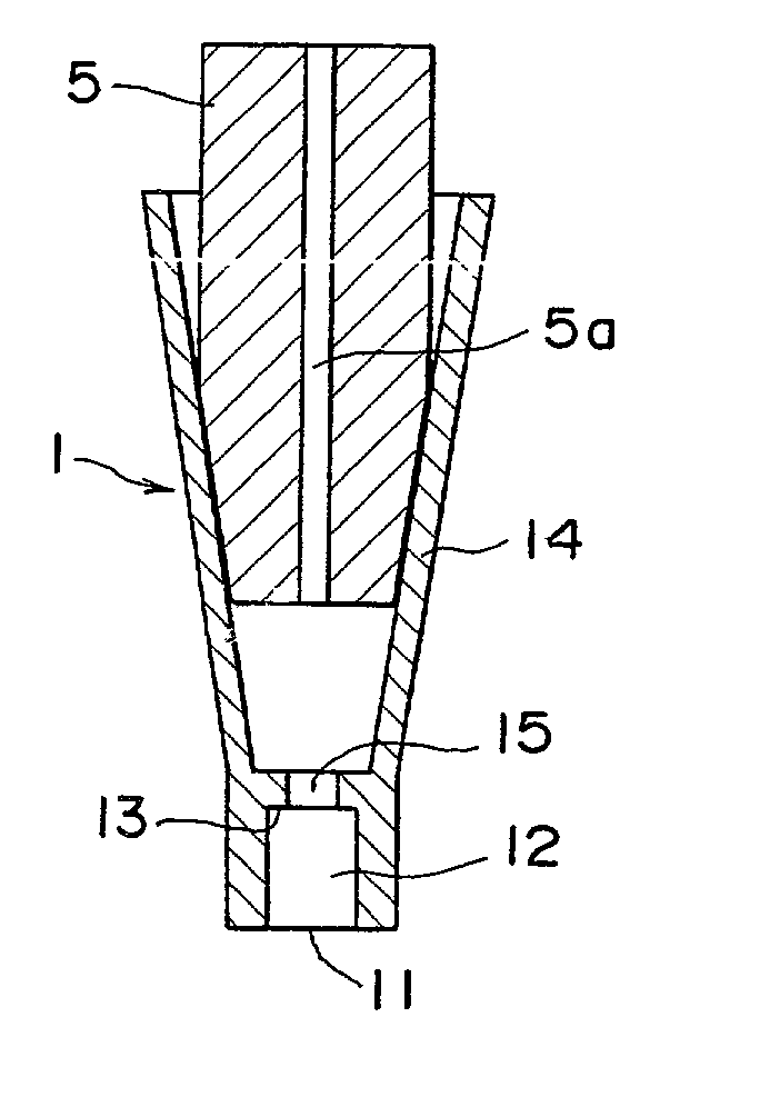
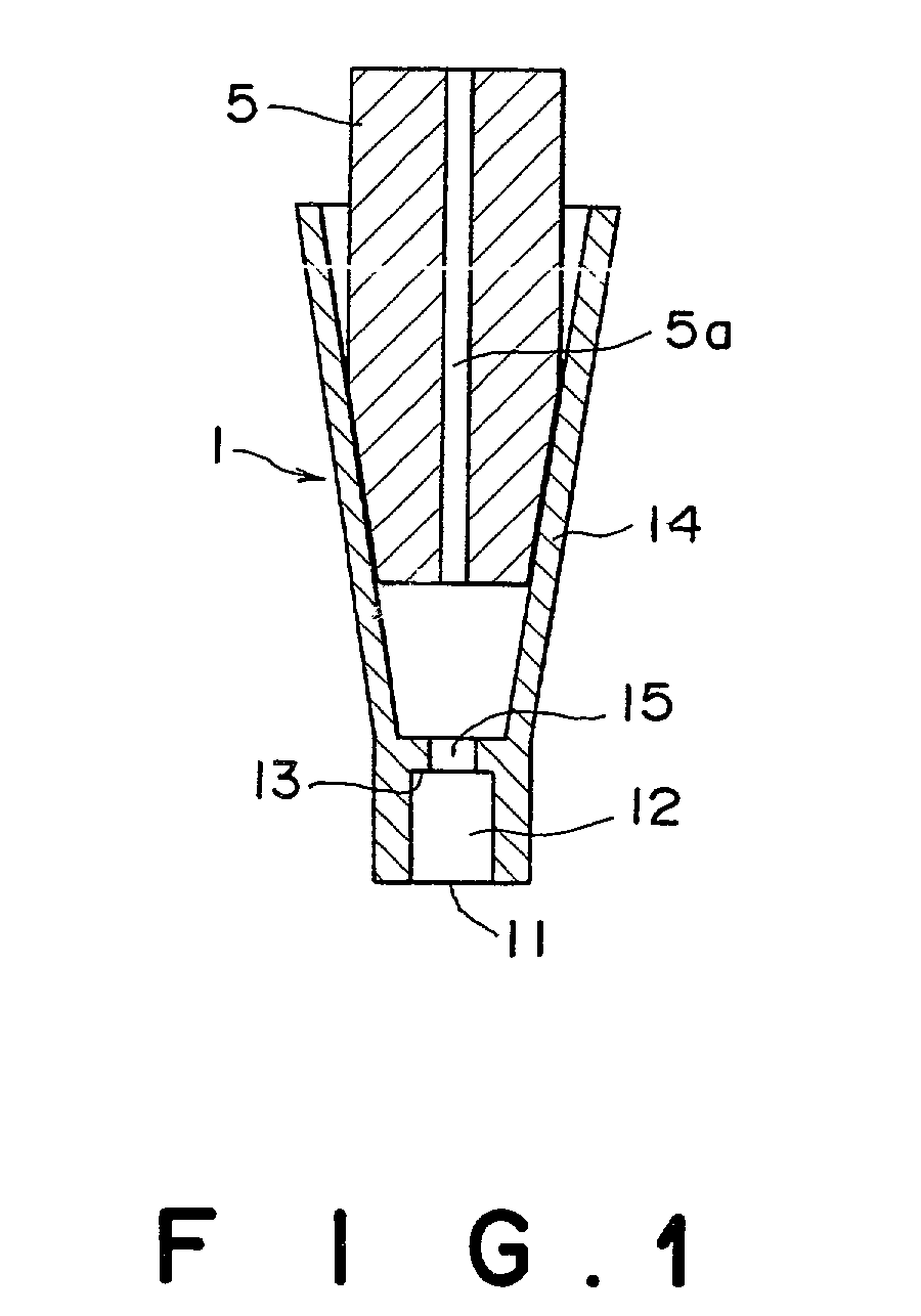
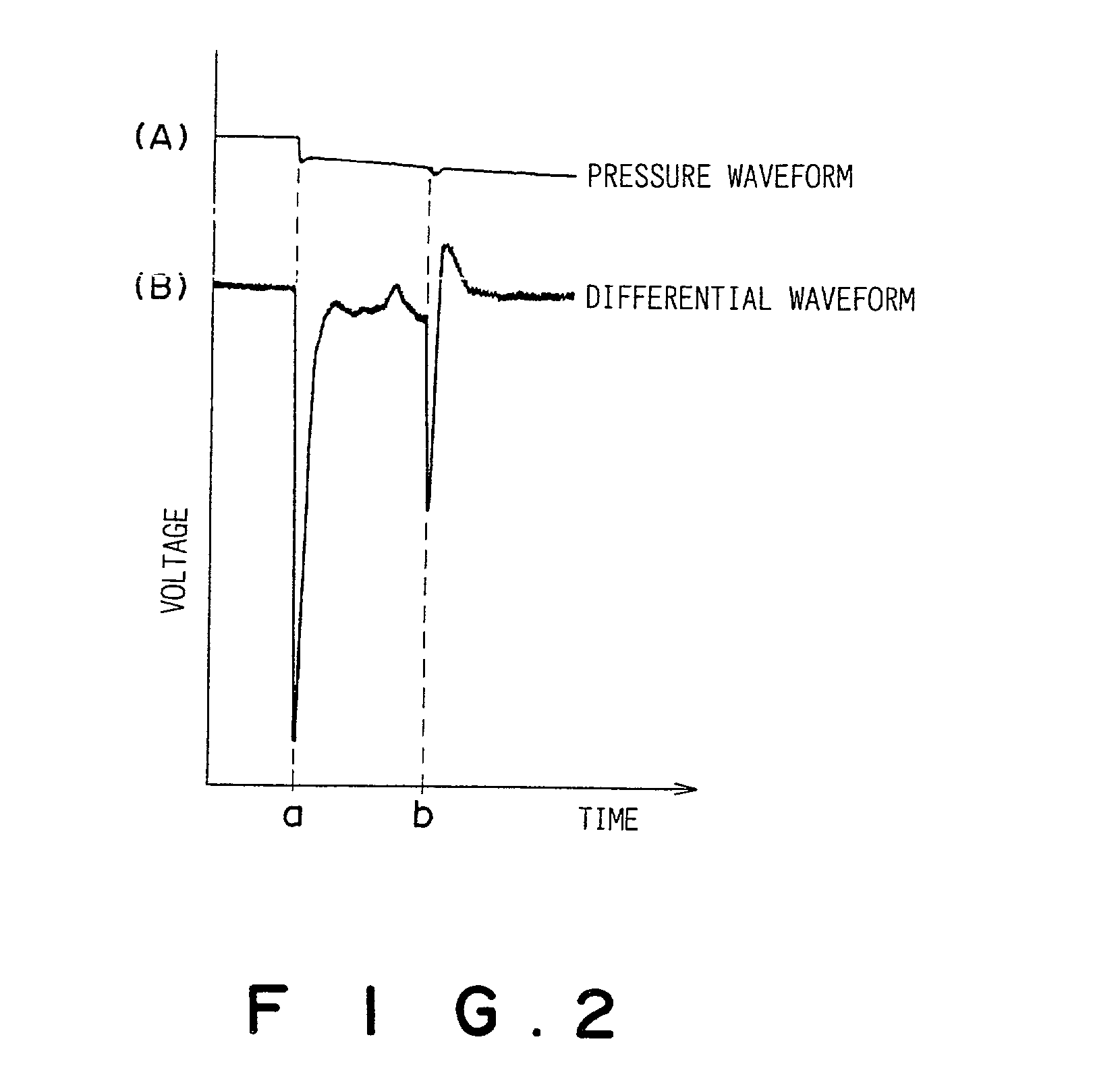
[0021] FIG. 1 is a cross-sectional view of an exemplary quantitative suction tip attached to the tip of a suction nozzle according to an embodiment of the invention. FIG. 2 is a graph plotting an example of pressure variation as a result of suction.

[0022] A quantitative suction tip 1 according to the present embodiment is similar to a pipet in overall shape. The quantitative suction tip 1 therefore has a suction opening 11 at the bottom into which a liquid flows. The suction opening 11 connects to a fixed volume chamber 12 with a predetermined volume. At the top of the fixed volume chamber 12 is provided a division wall 13. The division wall 13 is integrally formed with a fitting portion 14 provided thereon opposing a suction nozzle 5. The fitting portion 14 is conically shaped with a gradually increasing internal diameter, such that it can accommodate the tapered surface of the periphery of the tip of the suction nozzle 5 from above in a closely fitting manner. Thus the quantitativ...


PUM

PropertyMeasurementUnit
volumeaaaaaaaaaa
areaaaaaaaaaaa
suction pressureaaaaaaaaaa

Abstract

A quantitative suction tip to be attached onto the tip of a suction nozzle 5 comprises a fixed volume chamber 12 with a predetermined volume. The fixed volume chamber 12 has a suction opening formed at a lower end thereof and a division wall 13 formed at an upper end thereof. The division wall 13 has a through hole 15 which has a smaller cross-sectional area than that of the fixed volume chamber 12. As a liquid fills the fixed volume chamber 12 and reaches the through hole 15, there is caused a change in the suction pressure which is detected to terminate a suction operation. Thus, a predetermined quantity of the liquid can be accurately drawn into the quantitative suction tip without being affected by e.g. the surface tension and viscosity of the drawn liquid or the wettability of the inner walls of the quantitative suction tip.

Description

BACKGROUND OF THE INVENTION[0001] 1. Field of the Invention[0002] The present invention relates to a quantitative suction tip and a quantitative suction apparatus used for the drawing by suction of a predetermined quantity of liquids in an analysis apparatus and the like.[0003] 2. Description of the Prior Art[0004] In a quantitative analysis, for example, a predetermined quantity of a liquid such as that of a sample is often drawn by suction and then discharged as a drop onto an analysis element and the like. During such measurement, it is important to accurately draw and supply a predetermined quantity of a given liquid if the measurement accuracy is to be improved.[0005] In the prior art, such a quantitative suction of a liquid has been performed by using a suction pump such as a syringe. In this case, the spatial volume of the syringe is varied in proportion to a quantity of the liquid to be drawn, so that the resultant pressure can act on a suction nozzle to thereby draw the qua...

Claims


Application Information

Patent Timeline
Patent Type & Authority Applications(United States)
IPC IPC(8): B01L3/02G01N1/00G01N35/10
CPCB01L3/0275
Inventor KOMATSU, AKIHIRO
Owner FUJIFILM HLDG CORP
Why Eureka
Try Eureka