Buckle

a technology of buckle and sleeve, which is applied in the direction of fastenings, garment fasteners, press-button fasteners, etc., can solve the problems of high manufacturing cost, rigid buckle, harsh touch,

Inactive Publication Date: 2002-04-11
YKK CORP
View PDF0 Cites 27 Cited by
  • Summary
  • Abstract
  • Description
  • Claims
  • Application Information

AI Technical Summary

Problems solved by technology

Therefore, this buckle is rigid, harsh to the touch and does not have flexibility.
Further, the buckle shown in FIG. 26 involves such a problem that it requires many steps to be manufactured so that the manufacturing cost thereof becomes high.

Method used


Image

  • Buckle
  • Buckle
  • Buckle

Examples


first embodiment

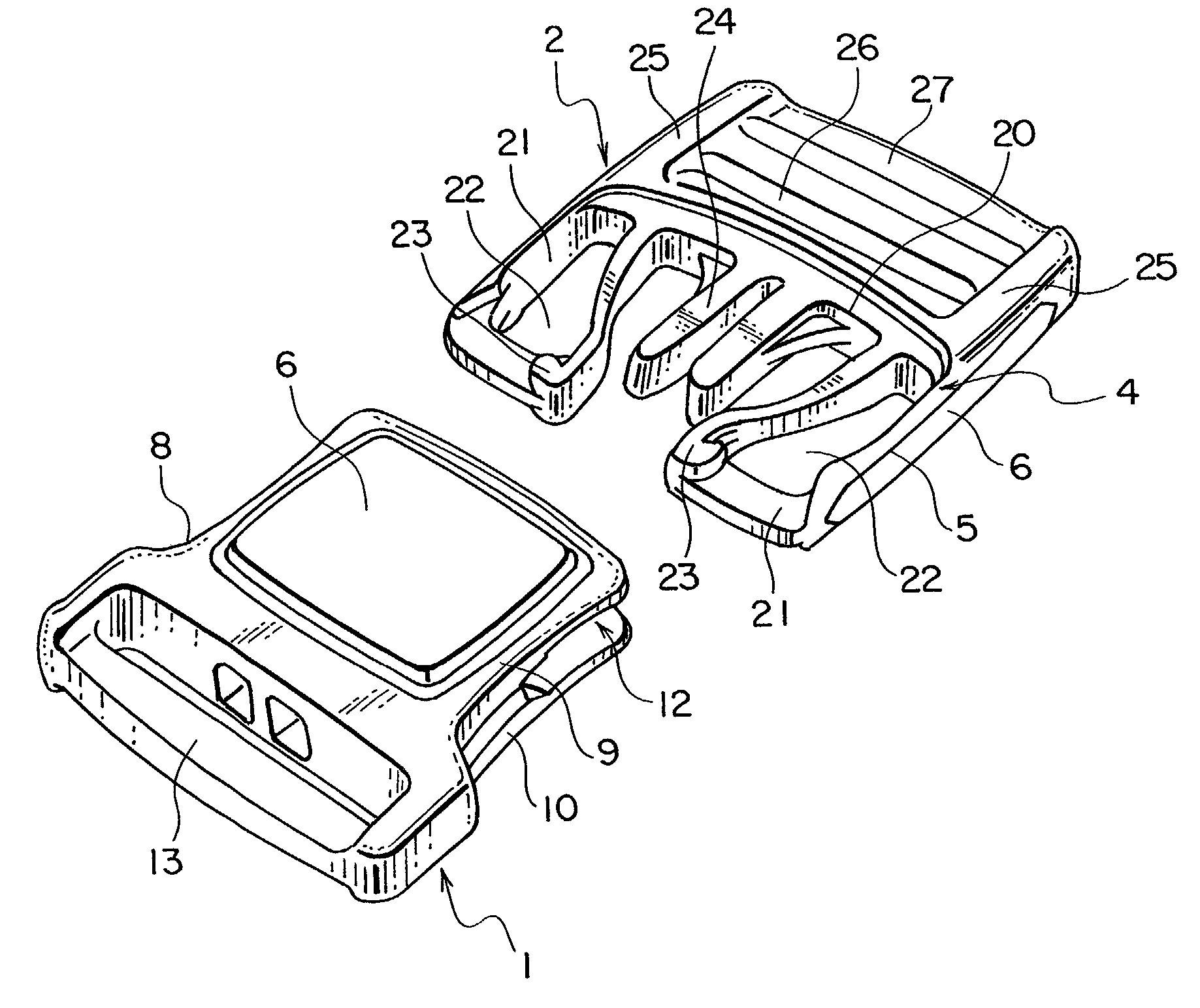
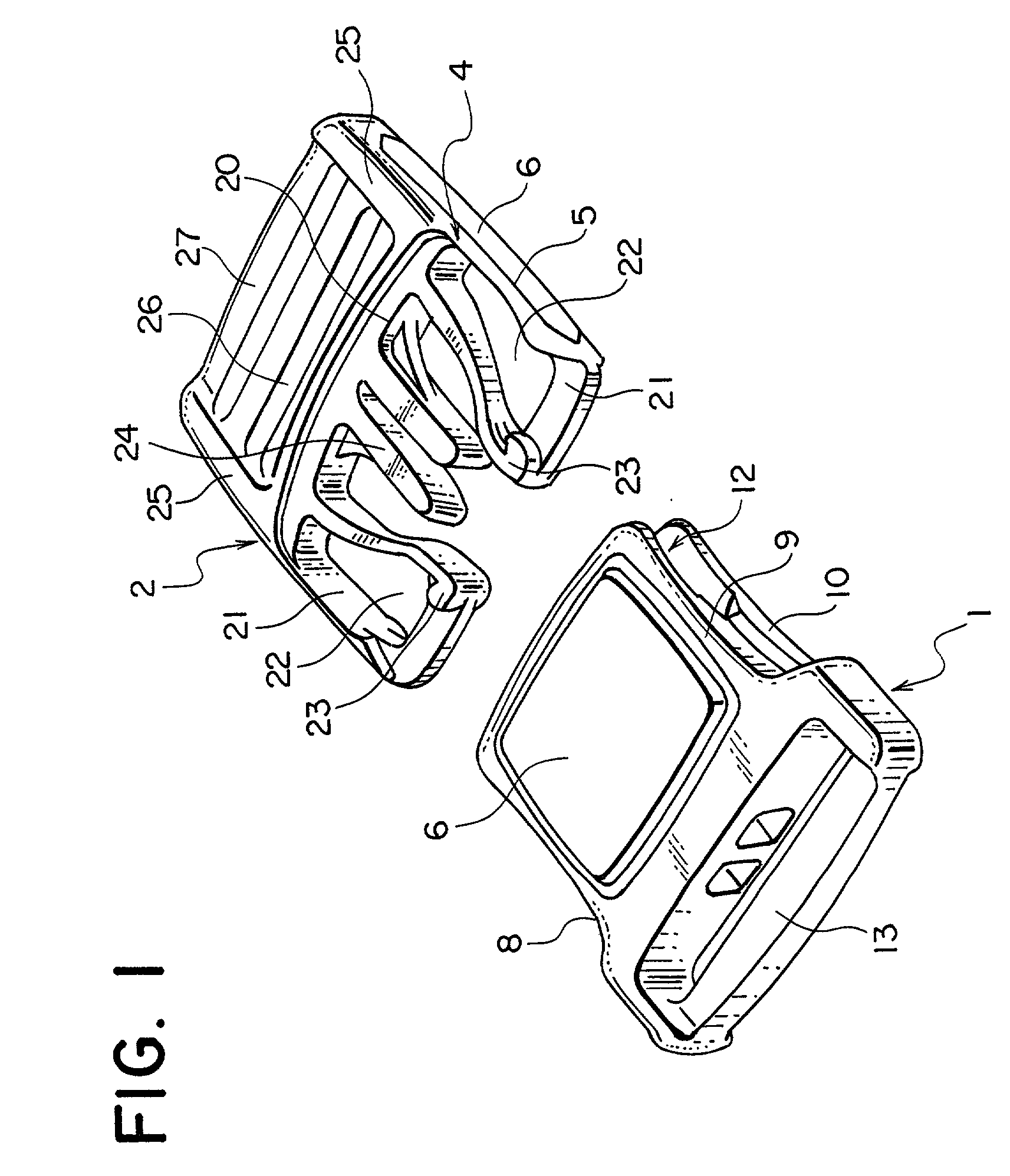
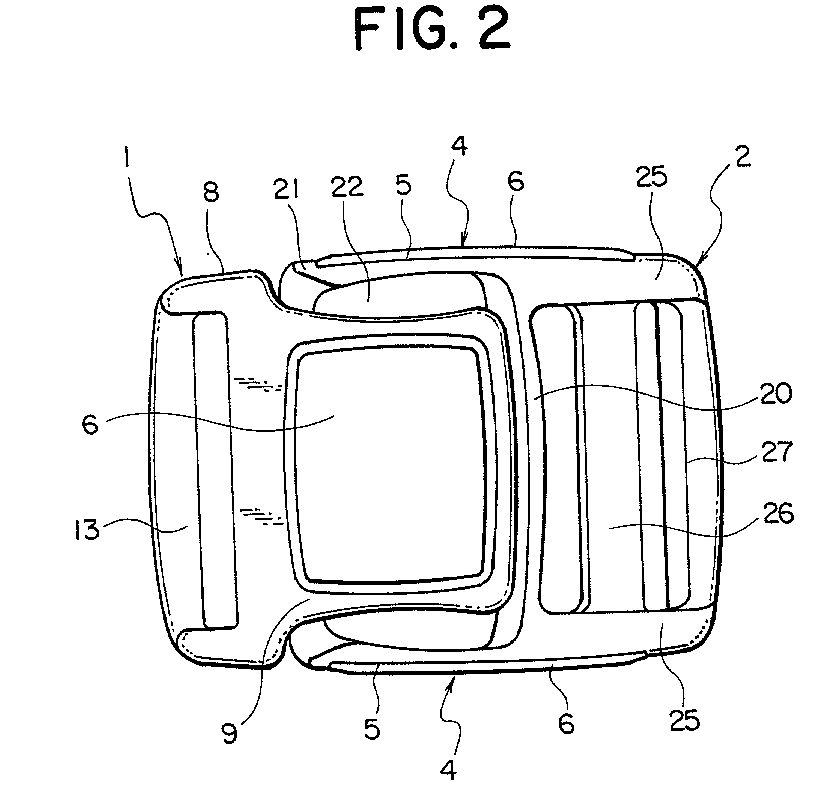
[0065] A buckle according to the present invention, which are shown in FIGS. 1 to 10, will be described below. The buckle body 1 is formed with a flat housing 8. As shown in FIGS. 4 and 7, the housing 8 is formed of a top plate 9 and a bottom plate 10 that are connected to each other with a middle partition 11 arranged at a center of the top plate 9 and the bottom plate 10 in a longitudinal direction thereof. The housing 8 is opened at three sides, namely, a front end and opposite sides thereof. Further, an insertion opening 12 is provided at one end of the housing 8 so that the insertion body 2 is capable of being inserted therein, while a belt attaching portion 13 is provided at the other end thereof so that the belt is capable of being attached thereto. Engaging portions 14, which are inwardly protruded and capable of being engaged with engaging protrusions 23 of the insertion body 2, are formed at inner opposite sides of the top plate 9 and the bottom plate 10. An elastic member...

second embodiment

[0070] According to a buckle of a second embodiment, which is shown in FIGS. 11 to 15, side levers 16 are provided at opposite sides of the housing 8 of the buckle body 1 as operating portions 4 to perform the engagement and disengagement operation of the insertion body 2. Elastic members 6 provided with elasticity are arranged on pressing surfaces 5 of the side levers 16. The buckle body 1 is formed with a flat housing 8 composed of a top plate 9, a bottom plate 10 and side walls 15. A middle partition 11 is provided at a center of the top plate 9 and the bottom plate 10 in a longitudinal direction thereof. The side levers 16, of which base portions are connected to the buckle body 1 and which are capable of being freely elastically deformed, are extended from side walls 15 at a side of an insertion opening 12 to a front end. Projections 17, which project inward, are provided on front ends of these side levers 16 so that the projections 17 can press insertion legs 21 of an insertio...

third embodiment

[0074] According to a buckle of the present invention shown in FIGS. 16 to 22, there is provided a pressing plate 17, which serves as an operating portion 4 for performing the engagement and disengagement operation of an insertion body 2, on a top plate 9 of a housing 8 of a buckle body 1. An elastic member 6 provided with elasticity is disposed on a pressing surface 5 of the pressing plate 17. The buckle is composed of the buckle body 1 and the insertion body 2. As shown in FIGS. 18 to 20, the buckle body 1 is provided with an insertion opening 12 at one end of a housing 8, into which an insertion plate 29 of the insertion body 2 is capable of being inserted. The top plate 9 is cut with slitters at three sides thereof except a side of the insertion opening 12, so that the pressing plate 17 is formed in a tongue shape having flexibility. The pressing surface 5 is formed on a surface of this pressing plate 17, and the elastic member 6 is integrally molded to be mounted on the pressin...


PUM


Abstract

A buckle is composed of a buckle body and an insertion body. The buckle includes an engagement and disengagement system in which the insertion body is inserted into the buckle body. An elastic member provided with elasticity, which is made of, for example, natural rubber, synthetic rubber or thermoplastic elastomer, is integrally molded on a pressing surface formed on an operating portion for performing an engagement and disengagement operation of the buckle by bicolor molding means or insert molding means. The pressing surface of the operating portion may be disposed on the buckle body or may be disposed on the insertion body. In either case, it is possible to produce a buckle having a good touch. Consequently, since the operating portion is flexible and soft to the touch, a smooth engagement and disengagement operation of the buckle can be realized.

Description

[0001] 1. Field of the Invention[0002] The present invention relates to a buckle having an engagement and disengagement system in which a male member, namely, an insertion body is inserted in a female member, namely, a buckle body. Particularly, the present invention relates to a buckle for fastening a belt that is generally used for clothes, a bag, a helmet, a baby buggy, sporting goods or the like.[0003] 2. Description of the Related Art[0004] FIG. 25 shows a conventional buckle with an engagement and disengagement system in which a pair of insertion legs 21' of an insertion body 2' are inserted in a housing 8' of a buckle body 1' thereof, which is disclosed in Japanese Design Registration Publication No. 984098. In the buckle, roughened surfaces having uneven faces 5a' are formed on outside surfaces of the insertion legs 21' so that the insertion legs 21' of the insertion body 2' can be easily handled in operation.[0005] Furthermore, FIG. 26 shows another conventional buckle of a...

Claims


Application Information

Patent Timeline
Patent Type & Authority Applications(United States)
IPC IPC(8): A44B11/26A44B11/25
CPCA44B11/266Y10T24/45702Y10T24/45581Y10T24/45524Y10T24/4556Y10T24/45864A44B11/26
Inventor UEHARA, RYOICHIROMATOBA, HIROSHI
Owner YKK CORP
Why Eureka
Try Eureka