
Method and apparatus for job preview in printer device

a printer device and job technology, applied in the direction of digital output to print units, instruments, computing, etc., can solve the problems of affecting the performance of the host platform, affecting the performance of the host for running other applications, and the preview image presented on the visual display unit may not be an accurate representation of the actual printed image to be printed, so as to reduce the performance cost requirement of the preview function

Inactive Publication Date: 2002-04-18
HEWLETT PACKARD DEV CO LP
View PDF9 Cites 70 Cited by
  • Summary
  • Abstract
  • Description
  • Claims
  • Application Information

AI Technical Summary

Benefits of technology

[0014] A further objective of the present invention may be to reduce the performance cost requirement of a preview function on a client computer terminal.
[0015] A further objective of the present invention may be to reduce resources needed on the printer platform to generate a preview image.
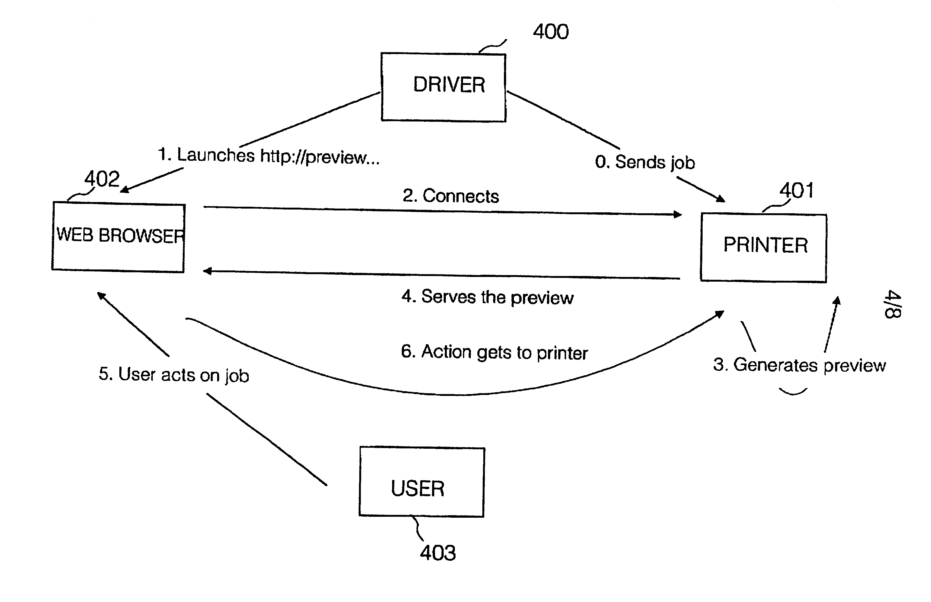
[0023] A preview is generated by a printer and accessed by a web browser resident on a client computer terminal, making it easy to get the preview from any host platform, with no further development cost at the host. As the preview is generated in the printer, it frees the host from generating the preview and leaves the host resources available for other tasks required by a user, for example running applications.
[0038] The invention aims to offer a means and apparatus for viewing an appearance on a user's print job, both during printing of the job, and / or before a page of print image is physically printed, so that no user time or print media e.g. paper or ink are wasted.

Problems solved by technology

Firstly, a preview image presented on a visual display unit may not be an accurate representation of an actual printed image to be printed by the printer. There may be differences between the preview visualised at a host computer, driving a printer, and the final image rendered in the printer. Such differences may be due to
Secondly, there is an impact on the performance of the host platform due to the rendering process.
Rendering of images is demanding upon processing power, and a rendering process carried out in a host computer may affect the performance of the host for running other applications.
There is a cost of development per platform in order to develop a plurality of renders.

Method used


Image

  • Method and apparatus for job preview in printer device
  • Method and apparatus for job preview in printer device
  • Method and apparatus for job preview in printer device

Examples


Embodiment Construction

[0047] There will now be described by way of example the best mode contemplated by the inventors for carrying out the invention. In the following description numerous specific details are set forth in order to provide a thorough understanding of the present invention. It will be apparent however, to one skilled in the art, that the present invention may be practiced without limitation to these specific details. In other instances, well known methods and structures have not been described in detail so as not to unnecessarily obscure the present invention.

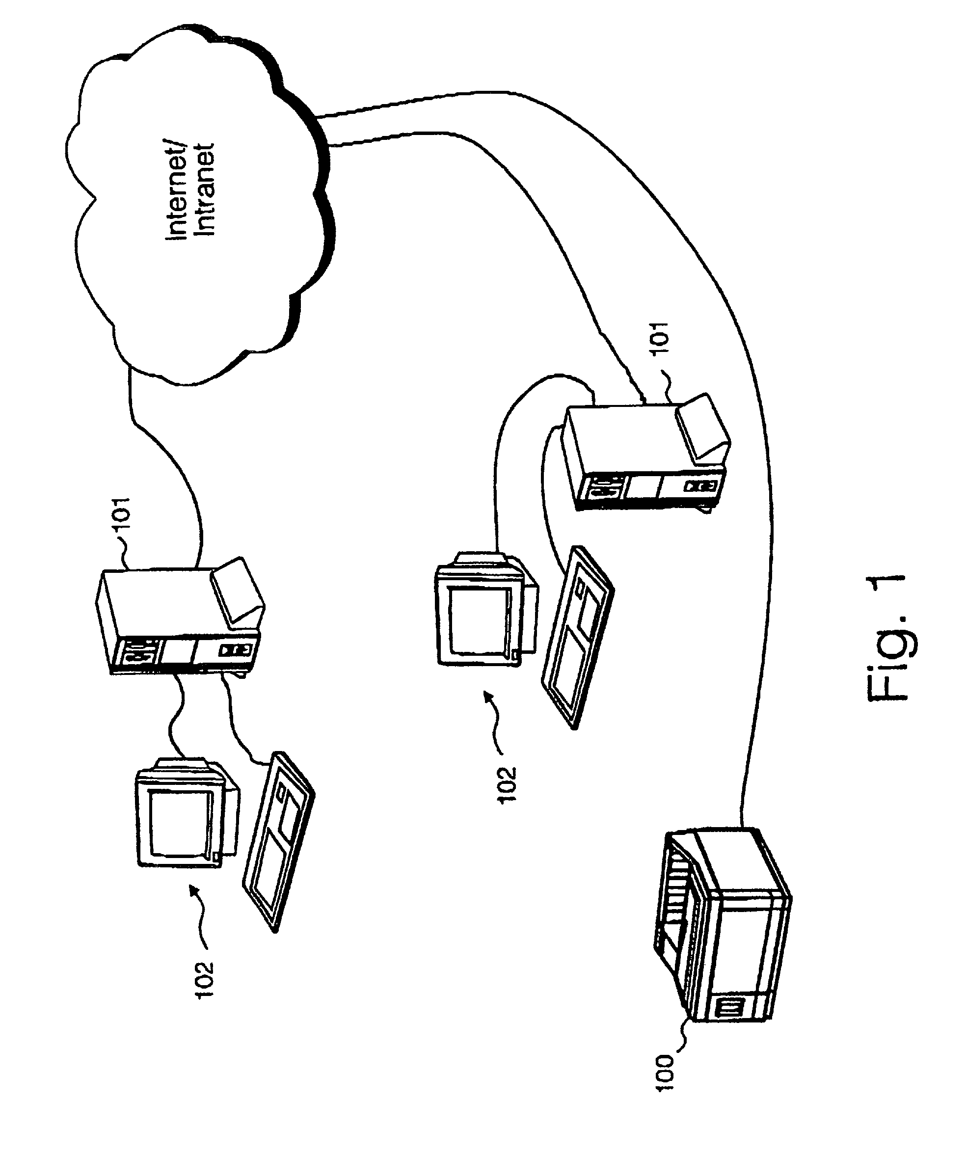
[0048] In this specification, the term `host computer` is used to describe any computer terminal which can communicate with a printer device, and having a web browser. The terms `host`, `host computer` and `client computer` are used interchangeably to mean the same thing and shall be construed accordingly.

[0049] Specific implementations of the invention provide a job preview visualization of a job as it will be actually printed on a ...


PUM


Abstract

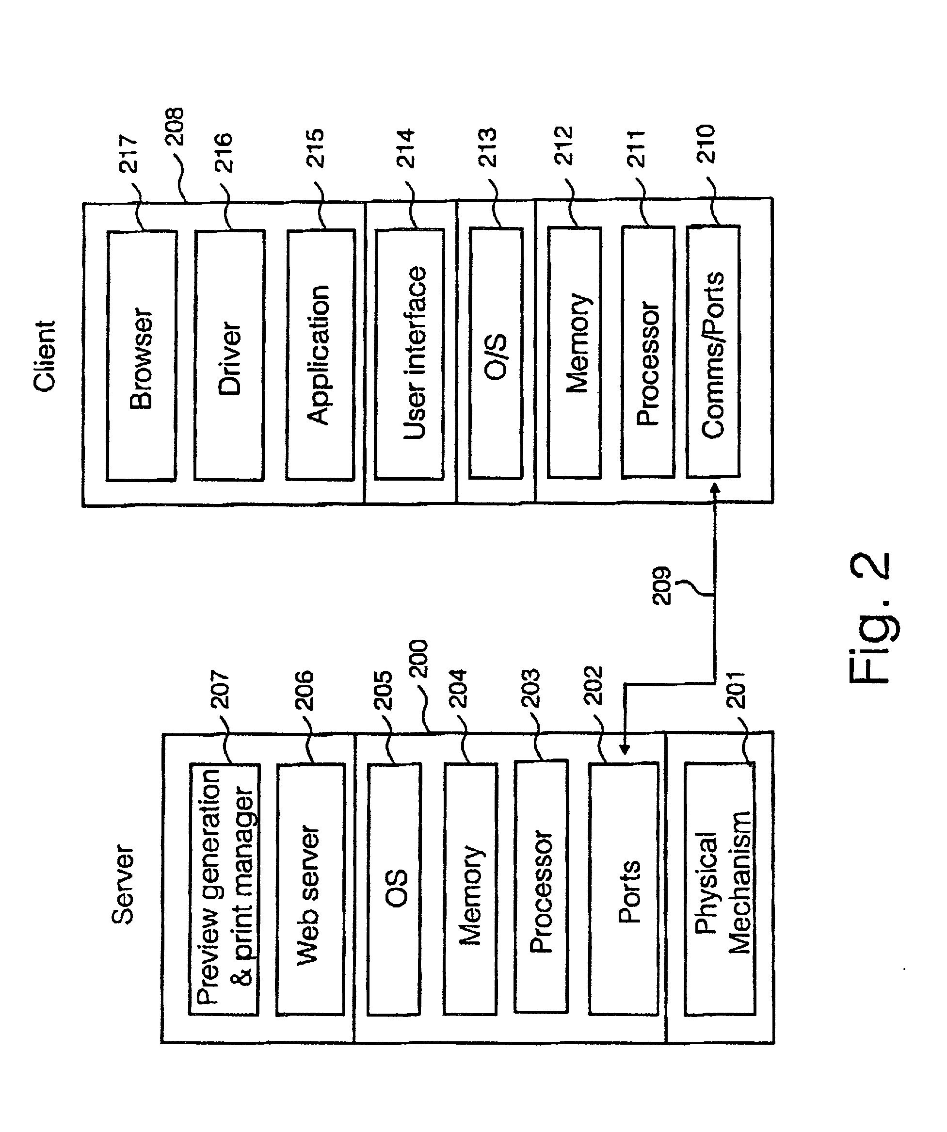
A printer device (200) is provided with a print manager module and preview generator module capable of generating a preview image of a print job in a form which accurately reflects the format and settings of the particular printer device. The print image is accessible via a web server (206) as an HTML page which can be viewed by a web browser on a client computer. A user may obtain a preview image on a visual display unit of the client computer which accurately describes a print image which will be printed by the printer device according to the local settings of that printer device.

Description

[0001] The present invention relates to the field of printers, and particularly although not exclusively to a method and apparatus for visualising a print image in a form in which the print image will be printed on a specific printer device.BACKGROUND TO THE INVENTION[0002] A print preview facility is known in many prior art raster image processor (RIP's) and in some known printer drivers. Such preview applications are run on host platforms, and operate by rendering an image print job before sending it to a printer, and allow a user to visualise the layout of the print job, and confirm the layout prior to printing. The user may cancel a print job after visualisation, or may confirm printing.[0003] There are several disadvantages with prior art preview solutions as follows:[0004] Firstly, a preview image presented on a visual display unit may not be an accurate representation of an actual printed image to be printed by the printer. There may be differences between the preview visuali...

Claims


Application Information

Patent Timeline
Patent Type & Authority Applications(United States)
IPC IPC(8): G06F3/12
CPCG06F3/1208G06F3/1288G06F3/1287G06F3/1256
Inventor ESTAVILLO, CRISTINAGOMEZ, XAVIER
Owner HEWLETT PACKARD DEV CO LP
Learn More