Optical Component Assembly for Use in a Direct Backlight Module

a technology of optical components and backlight modules, which is applied in the direction of luminescence, lighting and heating apparatus, instruments, etc., can solve the problems of increasing the voltage in the end of the tube, increasing the cost of the inverter, and affecting the overall uniformity of the panel, so as to reduce the amount of inverter disposed on both sides, the effect of reducing the amount of inverter

Inactive Publication Date: 2008-07-03
AU OPTRONICS CORP
View PDF6 Cites 0 Cited by
  • Summary
  • Abstract
  • Description
  • Claims
  • Application Information

AI Technical Summary

Benefits of technology

[0011]The primary objective of this invention is to provide an optical component assembly for use in a direct backlight module that has inverters disposed on one side.

Problems solved by technology

Although the inverters can be selectively disposed on either side or both sides, the inverters that are disposed on both sides will increase costs.
However, using single sided inverters will increase the voltage in the end of the tube which is adjacent to the inverter.
Due to this difference, when the backligh

Method used


Image

  • Optical Component Assembly for Use in a Direct Backlight Module
  • Optical Component Assembly for Use in a Direct Backlight Module
  • Optical Component Assembly for Use in a Direct Backlight Module

Examples


Embodiment Construction

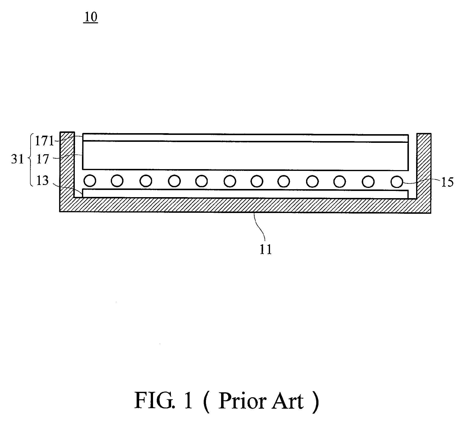
[0021]The direct backlight module enclosed in the present invention has a fundamental structure similar to the conventional backlight module. Please refer to the conventional structure as shown in FIG. 1 with the following descriptions to avoid superfluous descriptions.

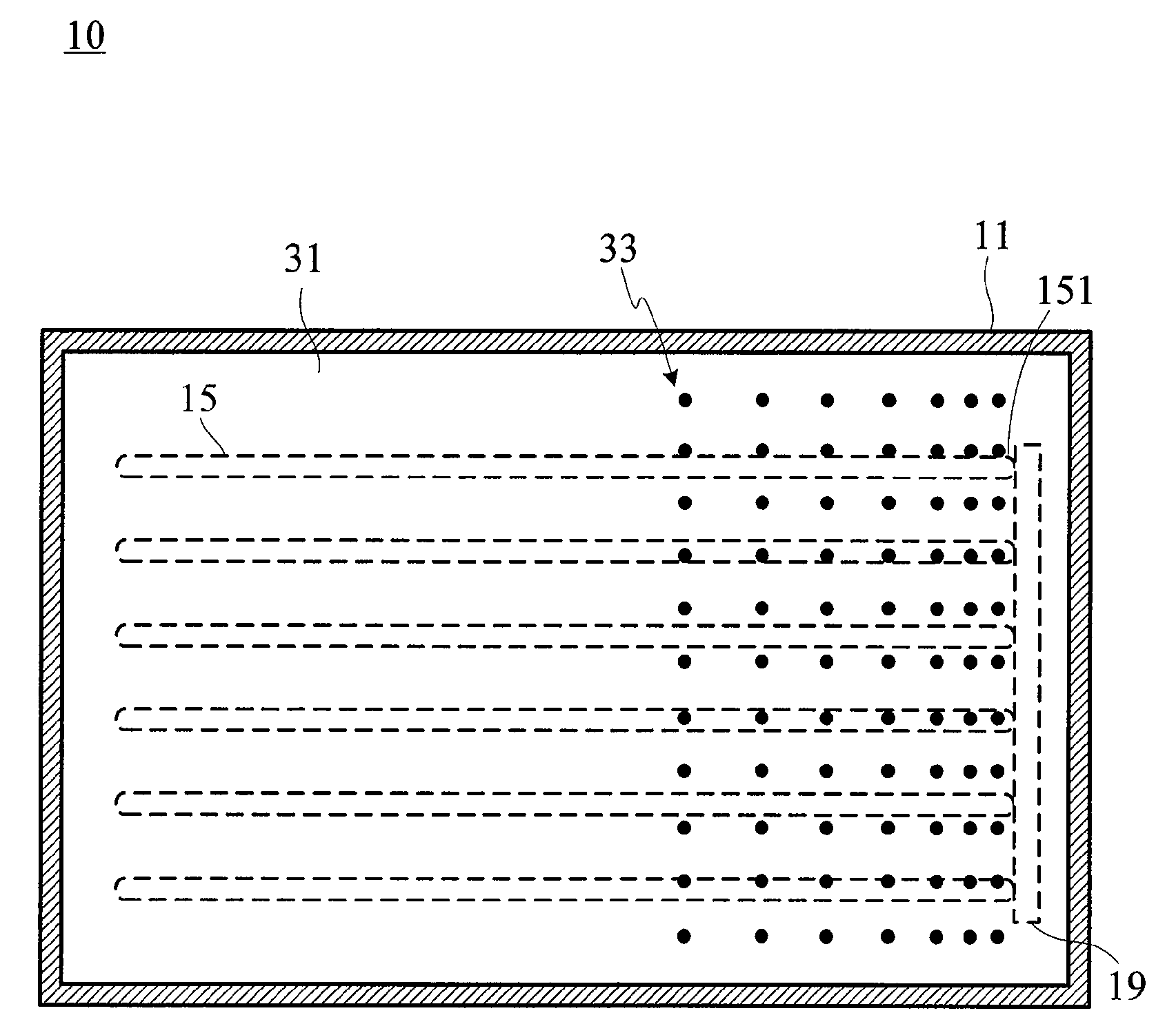
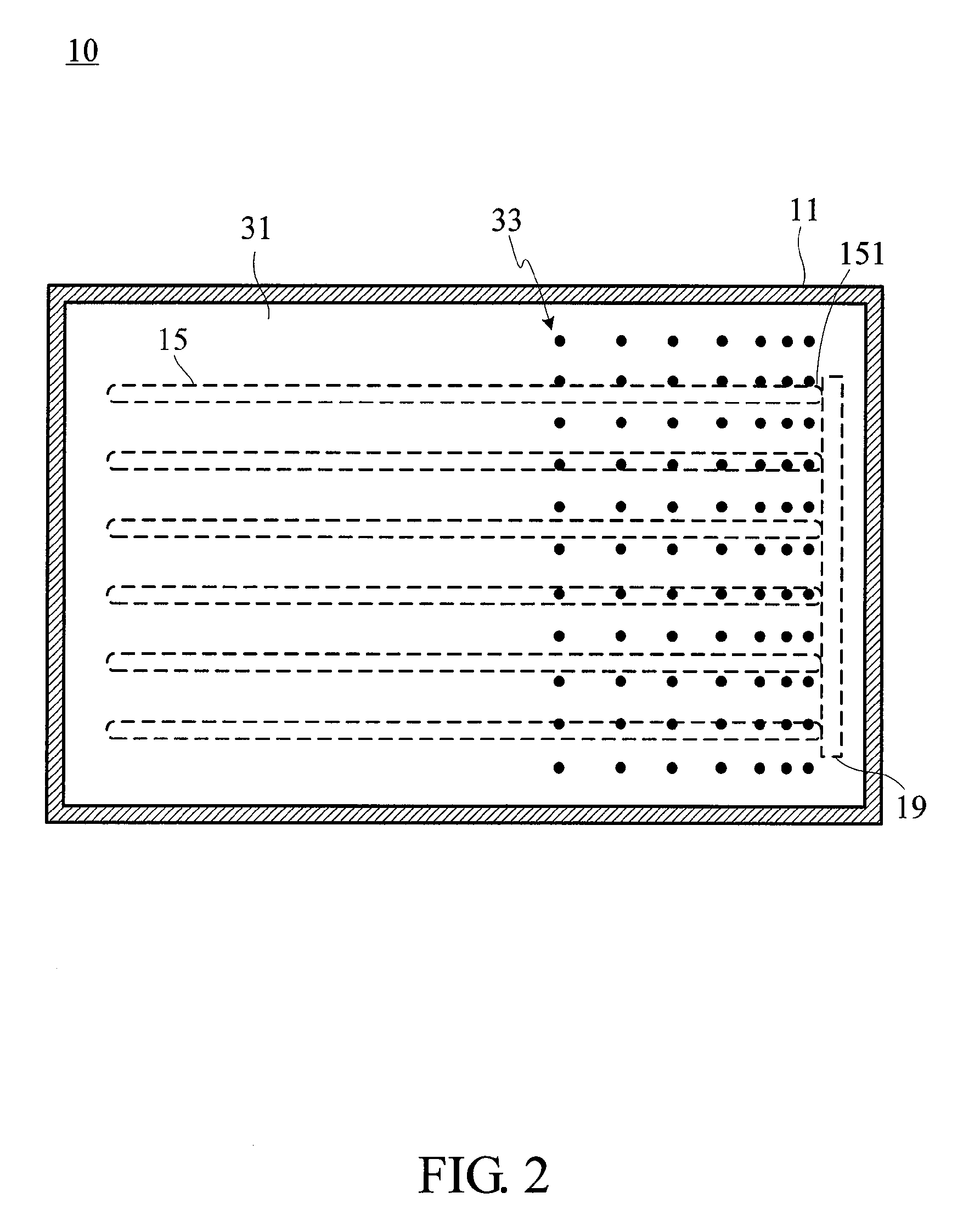
[0022]FIG. 2 shows a top view of an optical component assembly 31 of the present invention for use in a direct backlight module 10. The direct backlight module 10 comprises a light source 15 and a first driving unit 19 in a back bezel 11, wherein the light source 15 comprises a plurality of tubes which are substantially in parallel (dotted lines in figures only used to signify the locations). Preferably, the tubes are a plurality of cold cathode fluorescent lamps (CCFLs). For a direct backlight module 10 with single side driving, the first driving unit 19 electrically connects with the first end portion 151 of the light source 15 to provide a driving voltage for the light source 15 to generate light.

[0023]The optical ...


PUM


Abstract

An optical component assembly for use in a direct backlight module is provided. The optical component assembly possesses a light transmitting capability for projecting light emitted from the light source towards at least one specific direction. A pattern, which corresponds to the high-voltage end of the light source, is partially formed on the optical component assembly to retard light transmittance in part of the optical component assembly, and thus, improve the light uniformity provided by the backlight module.

Description

[0001]This application claims benefit from the priority of Taiwan Patent Application No. 095149558 filed on Dec. 28, 2006; the disclosures of which are incorporated by reference herein in their entirety.CROSS-REFERENCES TO RELATED APPLICATIONS[0002]Not applicable.BACKGROUND OF THE INVENTION[0003]1. Field of the Invention[0004]The present invention relates to an optical component assembly for use in a direct backlight module. In particular, the invention relates to an optical component assembly for use in a direct backlight module with single-side driven in a large sized liquid crystal display.[0005]2. Descriptions of the Related Art[0006]Liquid crystal displays (LCDs) have become increasingly popular because they not only save power and emit low radiation, but they are also lightweight and portable. In the past, the LCDs were popular in the small-sized display market only. Nowadays, LCDs have gained a larger market share in the large-sized display market with the progress of manufac...

Claims


Application Information

Patent Timeline
IPC IPC(8): G02B26/02
CPCG02F1/133604G02F1/133611G02F1/133606
Inventor SU, CHIH-CHIEHWU, CHIH KANG
Owner AU OPTRONICS CORP
Why Eureka
Try Eureka