
Data transmission method and data transmission apparatus

a data transmission apparatus and data transmission technology, applied in the field of data transmission, can solve the problems of large number of high cost, and large installation space of large optical signal transmission cables, and achieve the effect of avoiding large installation space, reducing and increasing the cost of data transmission systems

Inactive Publication Date: 2008-11-18
SONY CORP
View PDF8 Cites 1 Cited by
  • Summary
  • Abstract
  • Description
  • Claims
  • Application Information

AI Technical Summary

Benefits of technology

The present invention provides a method and apparatus for transmitting multiple optical signals using a single optical signal transmission cable. This allows for efficient bidirectional transmission of multiple optical signals, such as digital video signals, between a camera section and a signal recording and reproduction section. The method involves forming first to fourth word string data based on parallel data representative of the digital video signals, producing first to fourth serial data based on the word string data, converting the serial data into optical signals with center frequencies close to each other, and multiplexing the optical signals to create a multiplexed optical signal. The multiplexed optical signal is then transmitted through a bidirectional wavelength division multiplexing coupler to a receiver. The receiver demultiplexes the multiplexed optical signal back into the original optical signals, which are then converted into digital video signals and returned to the camera section or video recorder. The data transmission method and apparatus described in this patent text can be used in applications such as video transmission and recording.

Problems solved by technology

Further, digital data which form a digital video signal whose quantization bit number is 12, 14 or 16 involves a problem regarding transmission.
This also arises from the fact that it cannot be avoided to transmit the digital data which form the digital video signals or the digital video signals and Key signals divisionally in a plurality of channels.
Such arrangement of a large number of optical signal transmission cables requires a great cable installation space and a high cost.
However, no data transmission system of the type described is conventionally available.

Method used


Image

  • Data transmission method and data transmission apparatus
  • Data transmission method and data transmission apparatus
  • Data transmission method and data transmission apparatus

Examples


Embodiment Construction

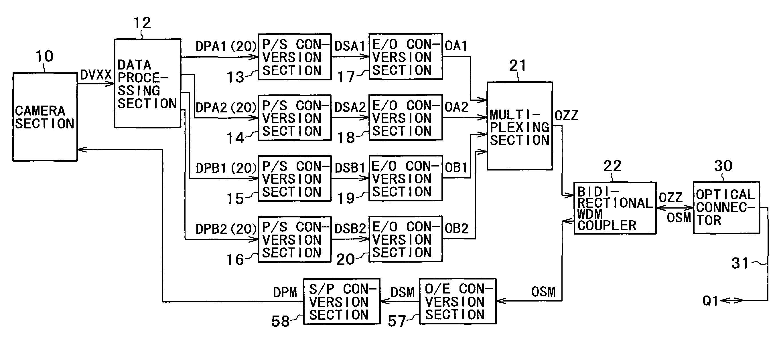
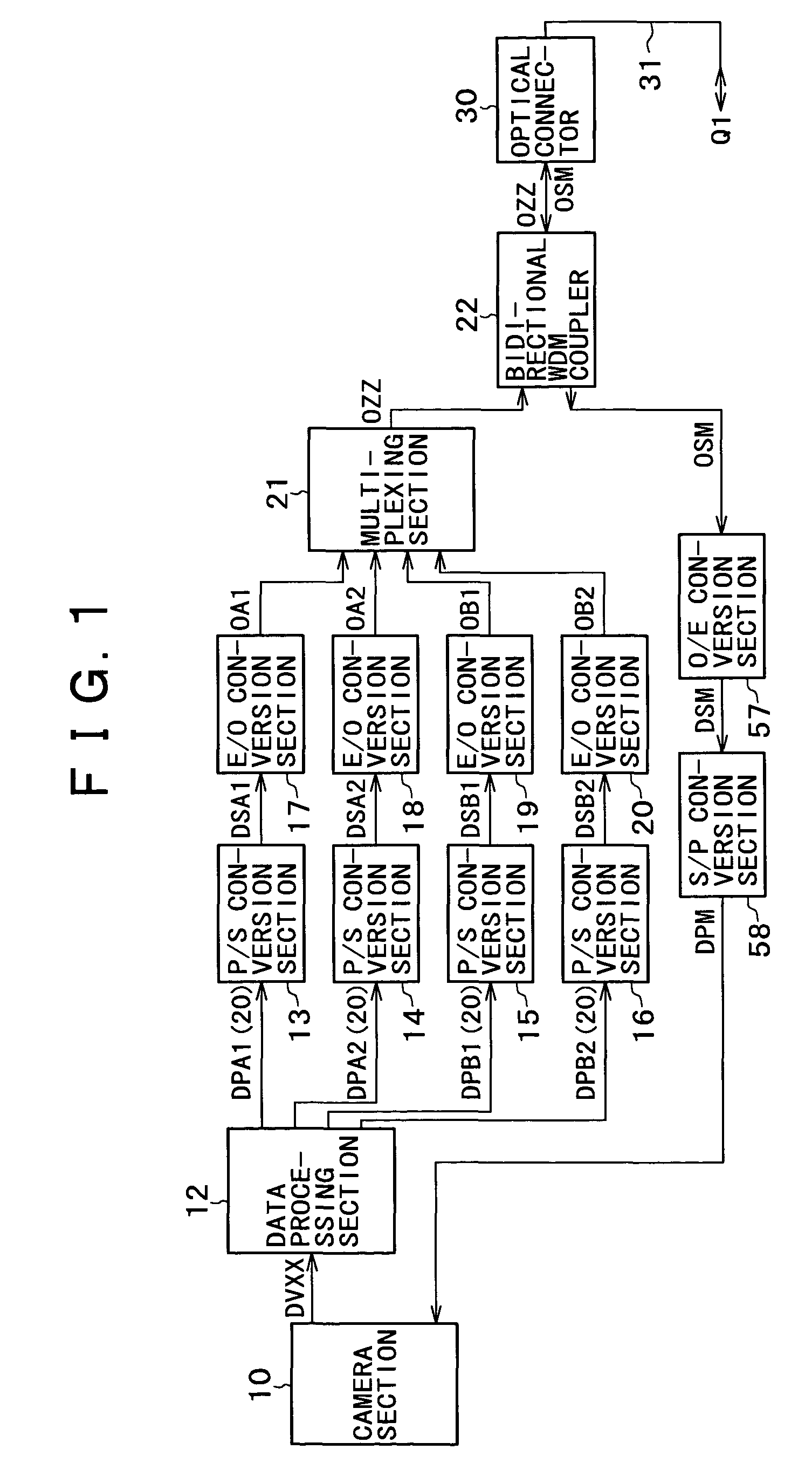
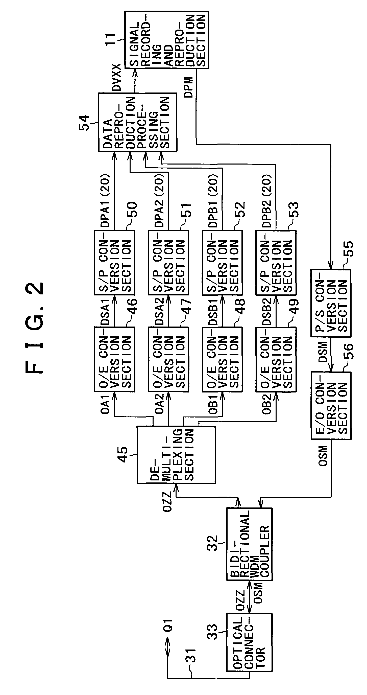
[0061]Referring first to FIGS. 1 and 2, there is shown a data transmission apparatus according to the present invention to which a data transmission method according to the present invention is applied.

[0062]The data transmission apparatus is used for bidirectional transmission of digital data between a camera section 10 and a signal recording and reproduction section 11. The bidirectional transmission is for the digital data, which form a D-Cinema signal, and digital data, which form a digital return video signal. The camera section 10 signals data DVXX while a data processing section 12 receives the data DVXX.

[0063]The data DVXX are parallel data which form, for example, D-Cinema signals indicated as one of data DC12, DC14, DC16, DD10, and DD12 in a table shown in FIG. 23. The D-Cinema signal is a digital video signal of the 4:2:2 format or the 4:4:4 format wherein the frame rate is set to 50 Hz or 60 Hz; the sampling frequency to 148.5 MHz; the effective data sample number in eac...


PUM


Abstract

A data transmission method and apparatus is disclosed by which bidirectional transmission of a plurality of optical signals obtained by conversion of a plurality of serial digital data can be achieved efficiently using a single common optical signal transmission cable. A plurality of serial data based on digital video signals from a camera section are converted into a plurality of optical signals using a CWDM technique and then multiplexed into a multiplexed optical signal. The multiplexed optical signal is signaled to a signal transmission cable through a bidirectional WDM coupler disposed at a first end of the optical signal transmission cable so as to be transmitted from the first end to a second end of the optical signal transmission cable. Further, serial data based on return video signals from a signal recording and reproduction section are converted into optical signals and then signaled to the optical signal transmission cable through another bidirectional WDM coupler disposed at the second end of the optical signal transmission cable. Consequently, the optical signals are transmitted from the second end to the first end of the optical signal transmission cable.

Description

BACKGROUND OF THE INVENTION[0001]This invention relates to a data transmission method wherein a plurality of optical signals obtained by converting a plurality of digital data representative of video signal information or like information into serial data and then opto-electrically converting the serial data are bidirectionally transmitted between two transmission / reception sections through an optical signal transmission cable and a data transmission apparatus for carrying out the data transmission method.[0002]In the field of video signals, digitalization is proceeding in order to achieve diversification of transmission information and higher picture quality of reproduction images. For example, a high definition television (HDTV) system which handles a digital video signal formed from digital data representative of video signal information has been proposed. A digital video signal under the HDTV system (a signal of the type mentioned is hereinafter referred to as HD digital video s...

Claims


Application Information

Patent Timeline
Patent Type & Authority Patents(United States)
IPC IPC(8): H04J14/02H04N7/22H04B10/00H04N21/647
CPCH04J14/02H04J14/0307
Inventor YAMASHITA, SHIGEYUKI
Owner SONY CORP
Learn More