Roller burnishing tool

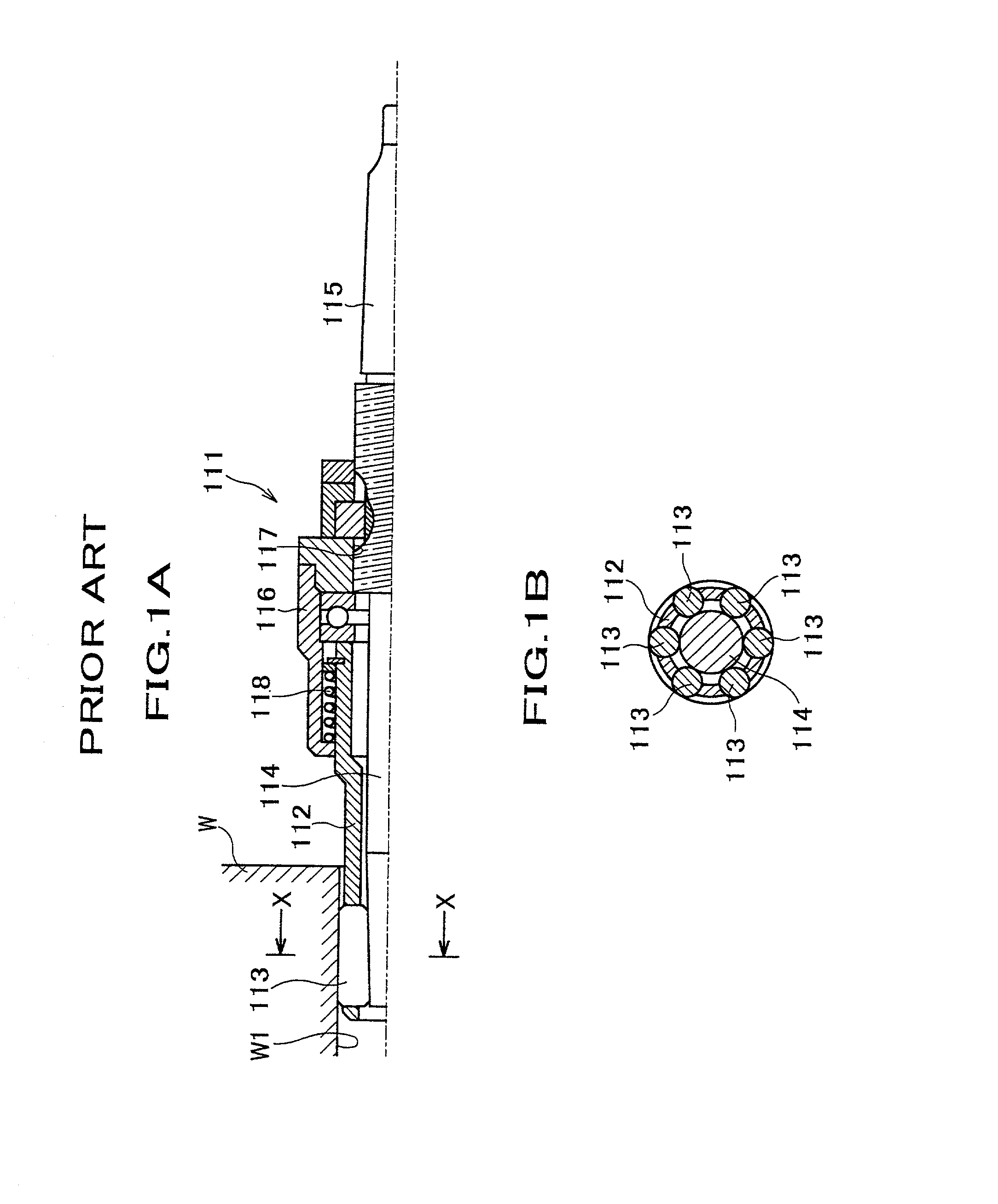
a technology of rolling tool and rolling pin, which is applied in the direction of burnishing machines, metal-working equipment, manufacturing tools, etc., can solve the problems of insufficient application of the mechanism outside the frame 112 to adjust the diameter of the rolling pin, inability to improve the efficiency of rapid rotation, and inability to apply the eccentricity of the work hole to achieve effective downsizing and lightening. , to achieve the effect of sustainable processing accuracy

Inactive Publication Date: 2002-04-25
SUGINO MACHINE
View PDF0 Cites 7 Cited by
  • Summary
  • Abstract
  • Description
  • Claims
  • Application Information

AI Technical Summary

Benefits of technology

[0020] Owning to the structure of driving a frame, it makes possible for rollers to perform a rapid feeding processing by the principle of a planetary motion compared with the structure of driving a conventional mandrel.
[0021] Of course owning to the structure of coaxially positioning the mandrel in the center axis of the frame improves a rotational accuracy which leads capable for a rapid rotation, and moreover, coaxially connecting the frame with shank portion of rotary drive improves a rotational accuracy which allows rollers to perform a rapid rotation with high accuracy.
[0022] Hence, whole efficiency is significantly improved compared with a conventional one.
[0023] In the second invention of this document, when reversing the rotation of said frame, a retreat force is generated in the mandrel by the agency of a feed angel .theta., the tool diameter is shrunken when this retreated force exceeds the impetus force of said elastic method. Accordingly, only reversing the rotation of the frame makes possible to easily withdraw frame from a work hole.
[0027] Moreover, In the third invention, since the mandrel is floating in a radial direction of the clearance between an inter diameter of the frame and the mandrel, processing accuracy is sustainable even under the condition of establishing a tool diameter on the position slightly slipped from the center of the work hole.

Problems solved by technology

In this way, however, the structure of positioning the mechanism outside frame 112 to adjust a tool diameter is not applicable for effective downsizing and lightening since the compression and downsizing of tool length has automatically limitation.
Hence, this can not be sufficiently applicable for an eccentricity of a work hole.
In addition, the improvement of an efficient rapid rotation is difficult since the tool rigidity is low due to the structure of imparting a rotary drive to a detailed mandrel 114 positioning along an axis of the frame 112.

Method used


Image

  • Roller burnishing tool
  • Roller burnishing tool
  • Roller burnishing tool

Examples


Embodiment Construction

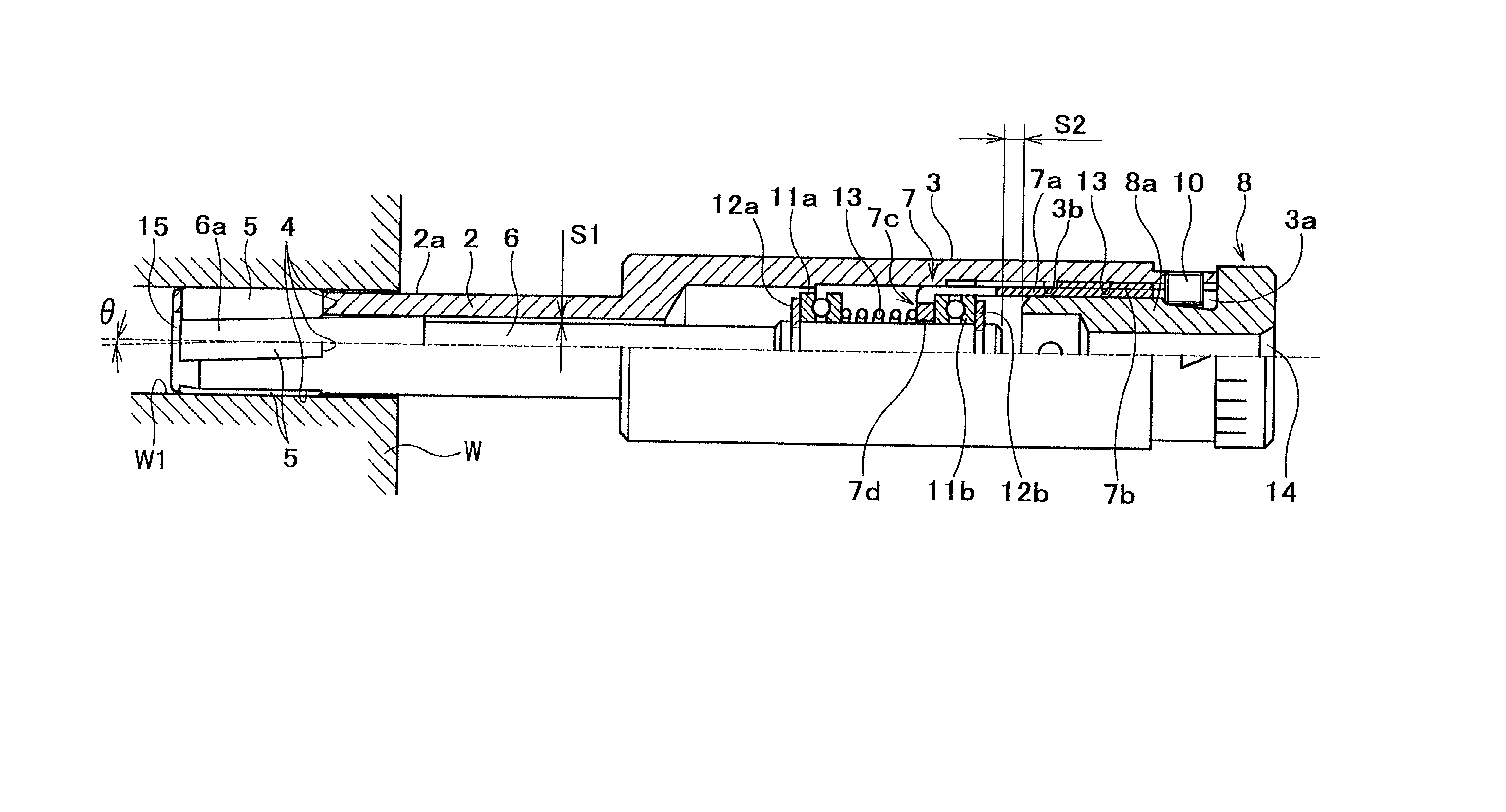
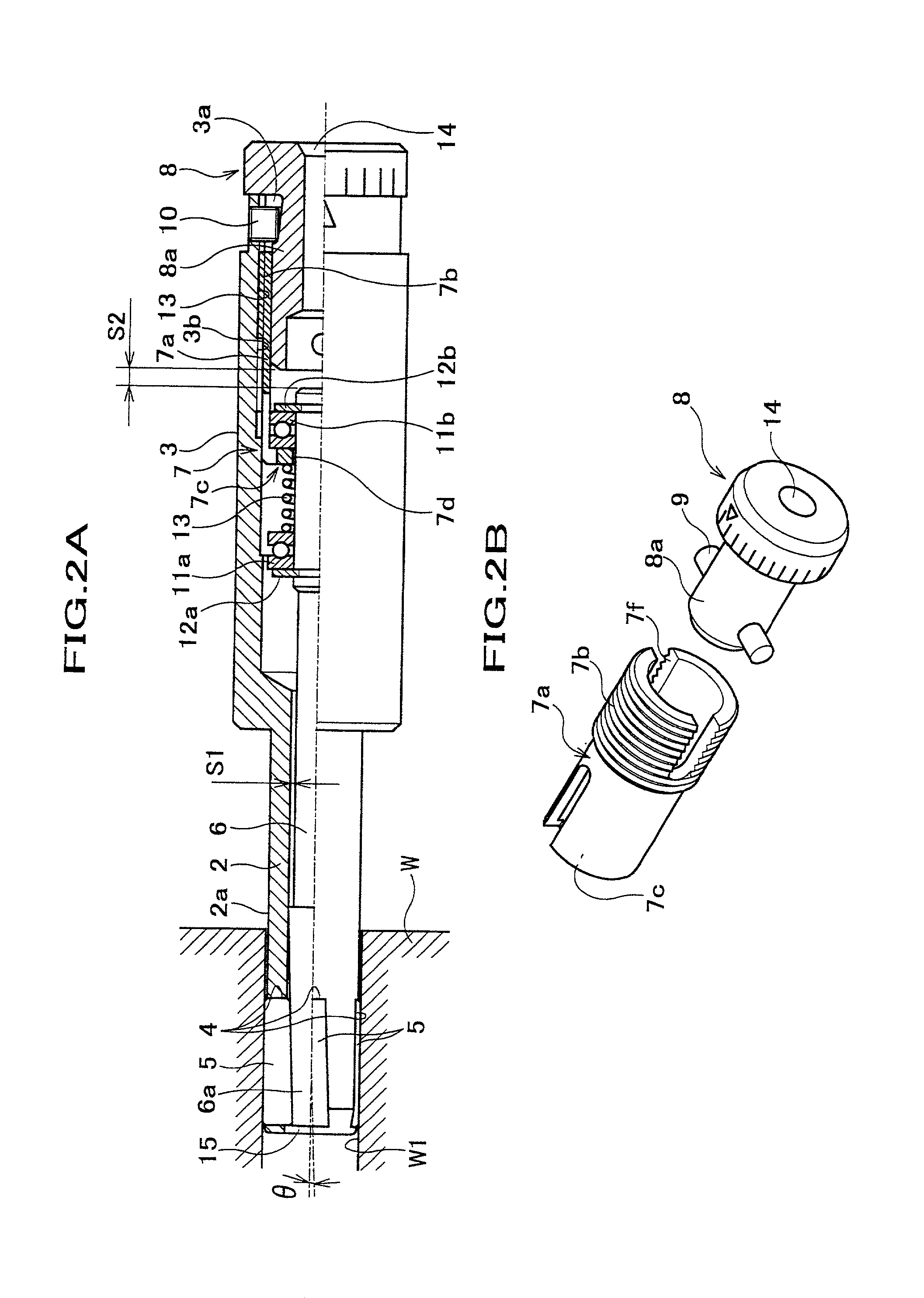
[0033] Following is the explanation of the implemented formation as reference to FIG. 2 to FIG. 5. FIG. 2 illustrates the roller-burnishing tool regarding to implemented formation. Like Illustration, the main body of the roller banishing tool 1 consists of the cylindrical frame 2 and the shank part 3, the frame 2 for a rolling compaction processing is coaxialy linked with a tip of the cylindrical shank part 3 to be driven by installing in the driving machine (not shown) of a machining hole, etc. The grooves 4,4 for engaging multiple rollers are provided in a circumferential direction at regular intervals along the tip of outer circumference 2a of said frame 2, the rollers 5 for rolling compaction machining are engaged with each groove 4,4 for engaging a roller in a radial direction with universal function for setting and rolling and rotation. Said grooves 4,4 for engaging roller are provided with a lean of predetermined angle .theta. against the axial line of said frame 2, said roll...


PUM

PropertyMeasurementUnit
diameteraaaaaaaaaa
circumferenceaaaaaaaaaa
internal diameteraaaaaaaaaa

Abstract

To provide a roller-burnishing tool, the usage by installing in a small machining center, small NC lathe and so forth is offered. The frame 2 for rolling compaction processing is coaxially connecting with the shank portion 3 which is performing a rotary drive by mounting in a driving machine, and the mandrel 6 is supported by this frame 2 with universal function for rotation. A tip end 6a of the mandrel 6 and the multiple roller 5,5 are formed into a taper shaped style for being supported by a rotation from a radial direction. The mandrel 6 and the compressing coil spring 13, which is impetuous from the shank portion 3 side to the frame 2 side are provided in the shank portion 3 as well as the adjustable ring 8, which is to adjust a tool diameter by moving the position of an axial direction to the frame 2 of the mandrel 6.

Description

[0001] 1. Field of Invention[0002] The present invention relates to a roller-burnishing tool to process an inner surface of a work hole, and more particularly to a roller-burnishing tool to finish inner holes of small parts in the wide range of fields such as automobile, home electronic appliance, semiconductor and so forth by a rolling compaction of multiple rollers.[0003] 2. Prior Art[0004] As this kind of a roller-burnishing tool, for example, such as the like indicated in Japanese Utility Model Publication No.64-275 is common.[0005] FIG. 1A and FIG. 1B illustrates this kind of roller-burnishing tool 111. The multiple rollers 113,113 to carry out a rolling compaction processing of an inner work hole W1 of a work W is engaged in a tip of an outer circumference of the cylindrical frame 112 with universal function for rising and setting and rotating, and the mandrel 114 formed as transmitting a rotary driving force is imbedded in said frame 112 with rotary supporting of these roller...

Claims


Application Information

Patent Timeline
Patent Type & Authority Applications(United States)
IPC IPC(8): B24B39/02
CPCY10T29/47B24B39/023B24B39/02
Inventor OKEDA, SHINICHIOKAJIMA, HIDEAKIWATABE, KOUKI
Owner SUGINO MACHINE
Why Eureka
Try Eureka