Shedding device in weaving machine

a technology of shedding device and weaving machine, which is applied in the direction of shedding mechanism, cam shedding mechanism, other shedding mechanism, etc., can solve the problems of deteriorating the durability of those members

Inactive Publication Date: 2002-04-25
TSUDAKOMA KOGYO KK
View PDF0 Cites 13 Cited by
  • Summary
  • Abstract
  • Description
  • Claims
  • Application Information

AI Technical Summary

Benefits of technology

[0016] By arranging the motors on the upper, lower, right and left sides, forming a rightward and leftward motor row with two or more motors, and relating the adjoining motors forming the motor row to heald frames not adjoining in the forward and backward direction within the heald frames corresponding to the support mechanisms, a distance between the heald frames relating to thus adjoining motors, in particular, a distance in the forward and backward direction is enlarged. Accordingly, a distance between the mechanisms for converting motion assembled to the output shafts of the motors and adjoining in the forward and backward direction can be enlarged.
[0017] As a result of the above, a mutual intervention of the mechanisms for converting motion individually assembled to the output shafts of the plural motors forming the motor rows can be prevented. Also, even if those mechanisms for converting motion transverse the front or the rear of at least one mechanism for converting motion, the sum of the thicknesses of the adjoining mechanisms for converting motion, in particular, the sum of the thicknesses of the members located near the output shafts of the motors among the members constituting those adjoining mechanisms for converting motion, is not limited to the arrangement pitch of the heald frames adjoining in the forward and backward direction. Furthermore, without enlarging the space to dispose the motors, the mechanical strength of the mechanisms for converting motion can be enhanced.
[0019] The second motor group and the motor group mentioned previously can be disposed in different positions at least in one direction selected from the forward and backward, upward and downward, and rightward and leftward directions. By doing so, many motors can be more efficiently arranged without lowering the strength of the members constituting the mechanisms for converting motion.
[0020] The motors in the same motor row can be arranged such that the motors nearer to the end portion of the connecting member on the side opposite to the motors are related to the heald frames on one of the forward side and the backward side nearer to the side where the motor group are arranged, among the heald frame corresponding to the support mechanism. This enables to prevent a mutual intervention of the mechanisms for converting motion relating to the motors within the same motor row more surely.

Problems solved by technology

Accordingly, the thicknesses of members including the eccentric wheel and the crank connecting rod must be made small, which deteriorates the durability of those members and causes a vibration.

Method used


Image

  • Shedding device in weaving machine
  • Shedding device in weaving machine
  • Shedding device in weaving machine

Examples


Embodiment Construction

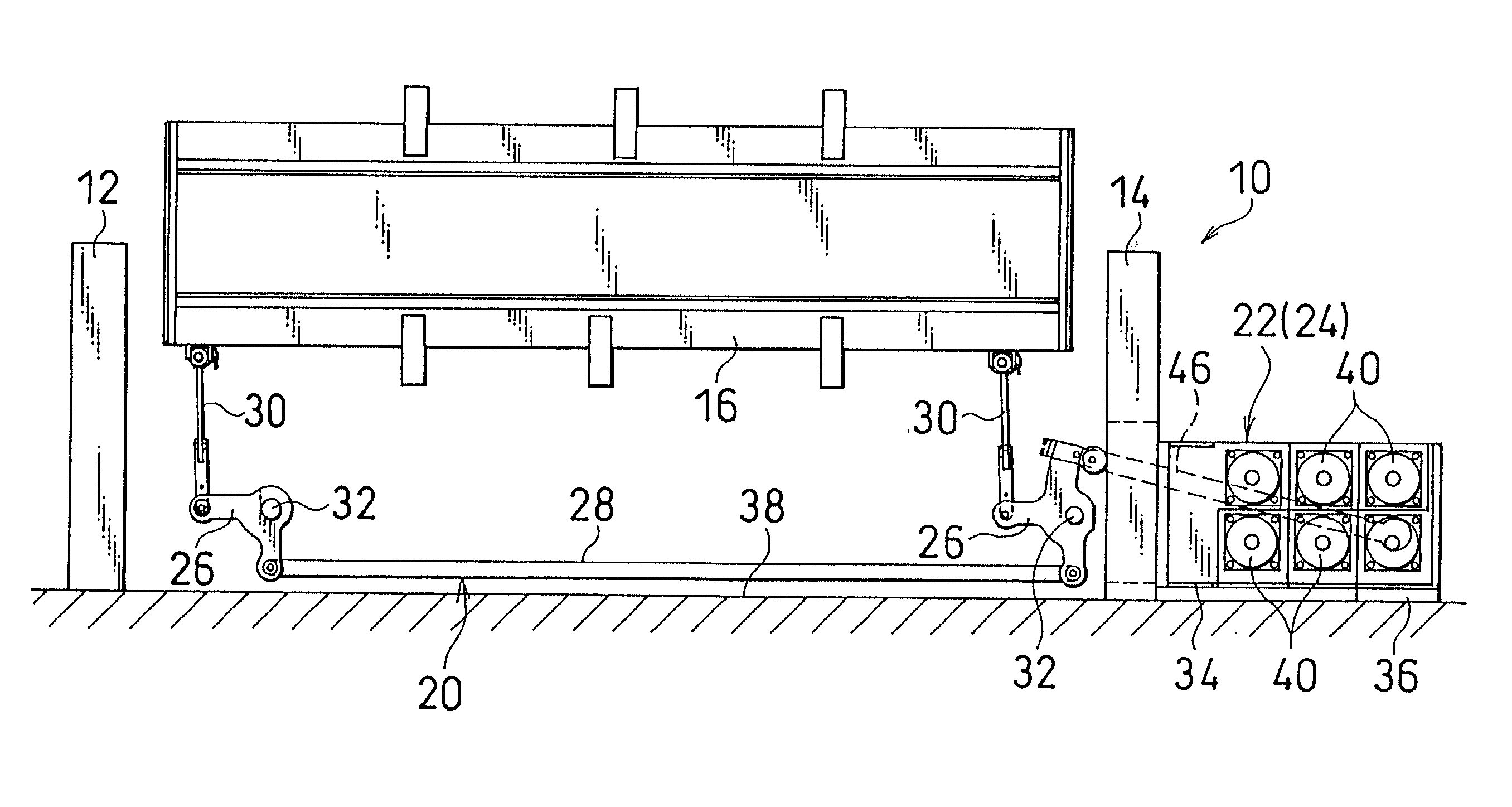
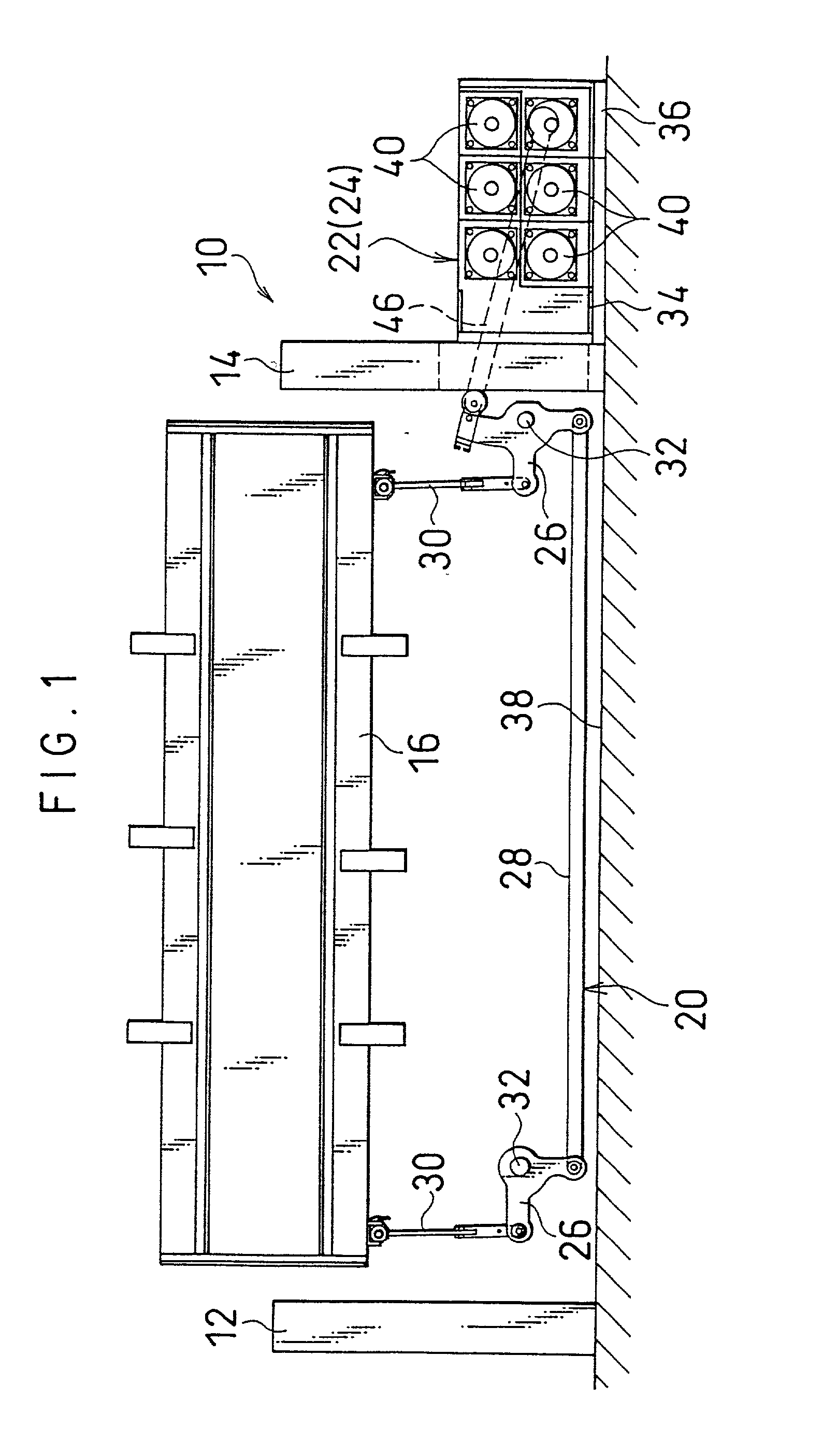
[0040] Referring to FIGS. 1 through 6, a shedding device 10 is used as an electric shedding device which forms a warp shedding by reciprocating upward and downward a plurality of heald frames 16 arranged at intervals in the forward and backward direction between right and left frames 12, 14 of the weaving machine together with the healds disposed on the heald frames 16. In FIG. 1, a warp is moved in a direction perpendicular to a sheet by a let-off from a warp beam not shown, while a weft is run from the left side to the right side or vice versa).

[0041] The heald frames 16 are divided, according to their arrangement positions in the forward and backward direction of the weaving machine, into a first heald frame group including a plurality of heald frames located on the forward side (cloth fell side) and a second heald frame group including a plurality of heald frames located on the backward side (opposite side to the cloth fell). In the illustration, the weaving machine includes twe...


PUM


Abstract

A shedding device in a weaving machine comprises one or more motor groups including a plurality of motors provided in every heald frame and directing their output shafts in the forward and backward direction of the weaving machine. The motors of each motor groups are arranged in the upward and downward, rightward and leftward directions, and two or more motors operating as at least part of the motor group are arranged in the longitudinal direction of a connecting member connecting the motors with support mechanisms of the heald frames to form one or more motor rows opposing to one or more connecting members, and adjoining motors in the motor row or rows are related to non-adjoining heald frames among the heald frames corresponding to the support mechanisms.

Description

[0001] 1. Field of the Invention[0002] The present invention relates to a shedding device for forming a warp shedding in a weaving machine.[0003] In this invention, a reciprocating direction of a heald frame is called a upward and downward direction; the moving direction of a warp by letting off of the warp, a forward and backward direction; the downstream side in a warp running direction, a front side; the upstream side in a warp running direction, a rear side; and a weaving width direction of the weaving machine, a rightward and leftward direction.[0004] 2. Description of Prior Art[0005] As one of devices for forming a warp shedding by moving a plurality of heald frames vertically is disclosed an electric shedding device in which each heald frame is supported by a support mechanism so as to move vertically and each support mechanism is driven by a drive motor provided at every heald frame (Japanese Patent Appln. PD (KOKAI) No. 10-130984).[0006] Each drive motor moves a correspondi...

Claims


Application Information

Patent Timeline
Patent Type & Authority Applications(United States)
IPC IPC(8): D03C5/00D03C13/00
CPCD03C5/00D03C13/025D03C13/00
Inventor HIRAI, JUN
Owner TSUDAKOMA KOGYO KK
Why Eureka
Try Eureka