Axial cooling of a rotor

a technology of axial cooling and rotor, which is applied in the direction of magnetic circuit rotating parts, dynamo-electric brake control, magnetic circuit shape/form/construction, etc., can solve the problems of water cooling cost, contribute to ventilation loss, and high cost of water cooling technology, so as to reduce the mass flow of air and reduce the ventilation loss

Inactive Publication Date: 2002-04-25
ABB (SCHWEIZ) AG
View PDF0 Cites 1 Cited by
  • Summary
  • Abstract
  • Description
  • Claims
  • Application Information

AI Technical Summary

Benefits of technology

[0004] The object of the invention is to provide air flow control by an air seal placed in the air gap between stator and rotor. The device reduces the mass flow of air that enters axially into the air gap. Used in conjunction with pole gap seals this will reduce the ventilation losses. Advantageous further developments of the invention are indicated in the following description.

Problems solved by technology

The relatively high peripheral speed of the rotor causes ventilation losses which consist partly of air gap friction losses and partly of a component which is proportional to the mass flow of air.
However, water cooling is expensive and technically complex, especially in the rotor.
Assuming that the stator is water-cooled, a drawback with this construction is that in the air gap between the stator and the rotor, an air flow will pass that serves no purpose, it only contributes to the ventilation losses.

Method used


Image

  • Axial cooling of a rotor
  • Axial cooling of a rotor

Examples


Embodiment Construction

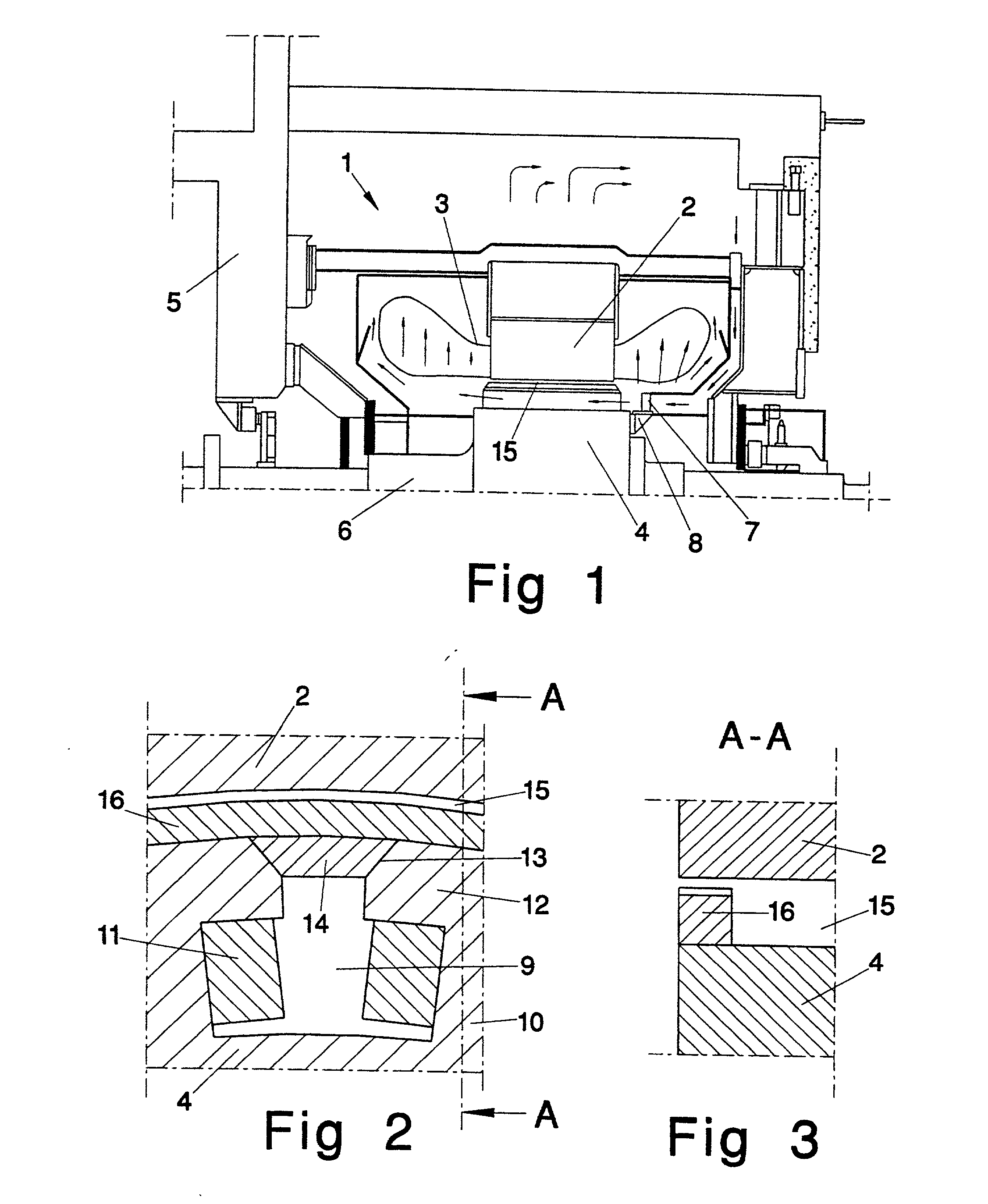
[0010] FIG. 1 shows a rotating electric machine 1 comprising a stator 2 with stator winding 3 which may consist of high-voltage cable. The machine 1 is provided with a rotor 4 arranged on a machine shaft 6 journalled in a machine housing 5. The rotor 4 is also provided with a fan 8 having blades 7. A controlled air flow for axial rotor cooling is indicated by arrows in the Figure. This also shows how the coil end parts of the machine are allowed to be cooled by the air flow. However, the invention is not limited to the embodiment shown in the drawing and according to a different embodiment the coil end parts can be cooled separately to avoid cooling one coil end with heated air. This can also be achieved by two-way axial cooling where each end of the rotor is provided with a fan blowing in air towards the middle of the rotor, the air then leaving through a radial air duct situated in the middle of the stator.

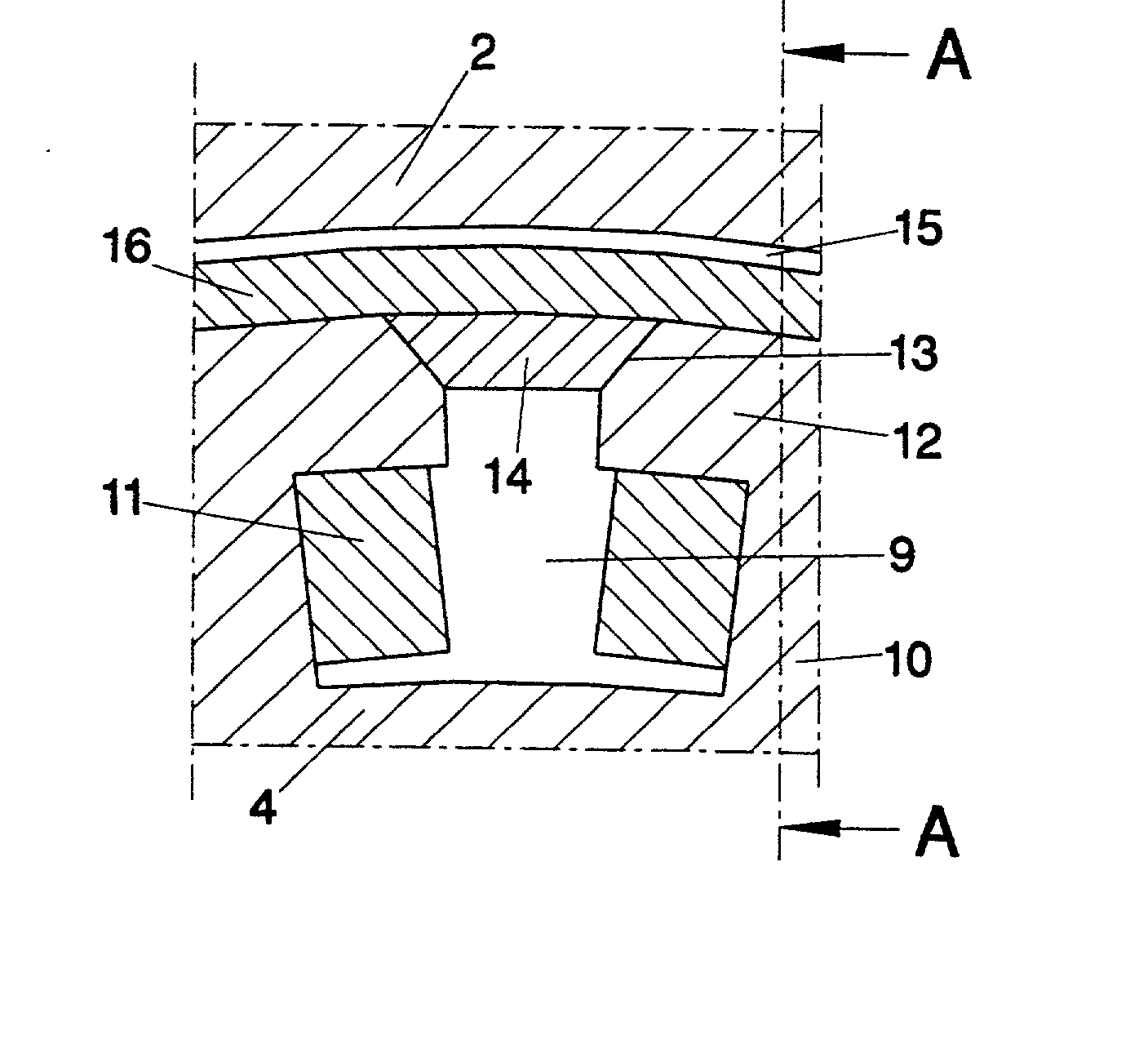
[0011] FIG. 2 shows a partial radial section through the rotor 4 which has ...


PUM


Abstract

A rotating electric machine (1) having a stator (2) provided with windings and a rotor (4) provided with windings and with salient poles (10) forming pole gaps (9) between the pole shoes (12) of the poles (10), which rotor (4) is arranged to be cooled by air flowing axially through the pole gaps (9) of the rotor (4), wherein each pole gap (9) between the pole shoes (12) is covered by at least one covering member (14) and that the air gap (15) is equipped with a sealing ring (16) to limit axial air flow.

Description

TECHNICAL FIELD[0001] The present invention relates to large rotating electrical machines equipped with salient pole rotors such as synchronous motors used in industry and synchronous generators used in hydro power plants. The invention relates particularly to a design for controlling the cooling air flow in the rotor by choking the air flow in the air gap and sealing the gaps between adjacent poles.BACKGROUND ART[0002] Synchronous machines with salient pole rotors are normally cooled with air. Large such machines have radial cooling ducts in the stator. The air is delivered to the stator ducts by first passing axially through the pole gaps in the rotor. In the pole gaps, the air passes axially along the field windings, thereby cooling them. The relatively high peripheral speed of the rotor causes ventilation losses which consist partly of air gap friction losses and partly of a component which is proportional to the mass flow of air.[0003] In order to minimize the ventilation losse...

Claims


Application Information

Patent Timeline
Patent Type & Authority Applications(United States)
IPC IPC(8): H02K1/32H02K9/06
CPCH02K1/325
Inventor KYLANDER, GUNNARLEIJON, MATS
Owner ABB (SCHWEIZ) AG
Why Eureka
Try Eureka