Two-dimensional code extracting method

a two-dimensional code and extraction method technology, applied in image enhancement, image analysis, instruments, etc., can solve the problem that software or hardware intended to restore the data to its original state cannot restore the scanned data properly

Inactive Publication Date: 2002-05-02
FUJITSU LTD
View PDF4 Cites 43 Cited by
  • Summary
  • Abstract
  • Description
  • Claims
  • Application Information

AI Technical Summary

Benefits of technology

0015] Also, in the present invention, the detected two-dimensional code region is scanned from a point within the above-mentioned two-dimensional code region block by block having a predetermined size toward upward, downward, to the right and to the left of the a...

Problems solved by technology

When images other than the two-dimensional codes are included in the scanned data, the software or hardware intended to restore the data to its...

Method used


Image

  • Two-dimensional code extracting method
  • Two-dimensional code extracting method
  • Two-dimensional code extracting method

Examples


first embodiment

[0097] FIG. 9 is a process flow diagram 400 showing the process for detecting two-dimensional code regions of the present invention. The process flow diagram shown in FIG. 9 corresponds to the S103 process shown in FIG. 3.

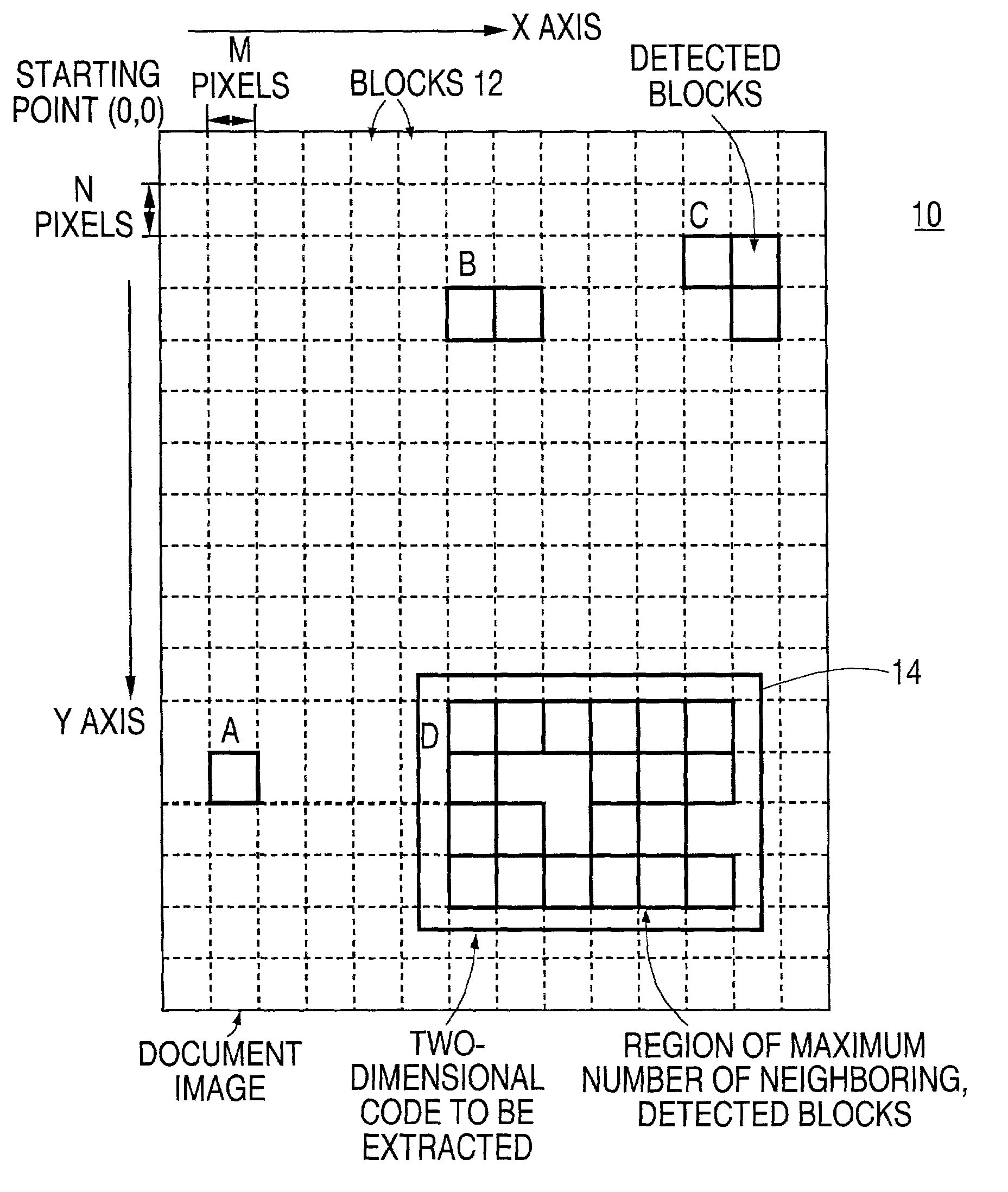
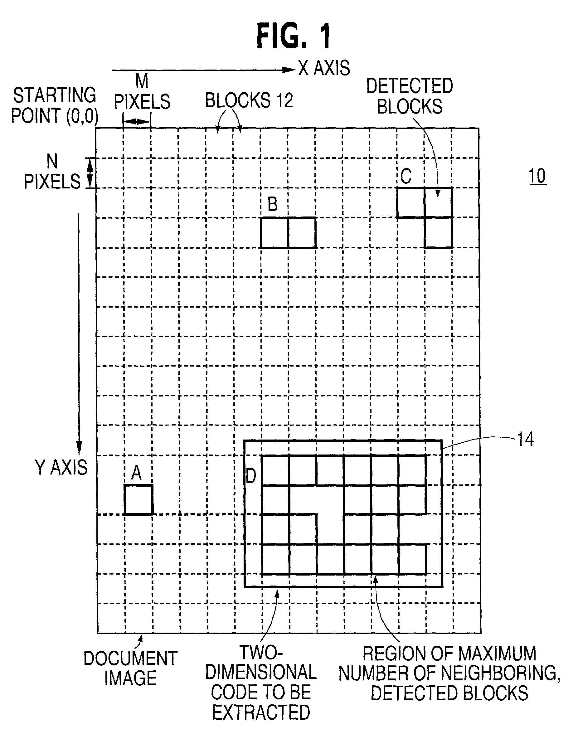
[0098] In S401, the block information table 210 is referenced. The maximum number of contiguous blocks is set to Rmax. In the block information table 210 shown in FIG. 8, Rmax is 20.

[0099] In S402, the maximum values (Xmax and Ymax) and the minimum values (Xmin and Ymin) for the X coordinates and Y coordinates are calculated in the block where the contiguous block number matches Rmax. In FIG. 8, the coordinates of block 6 (X6, Y6) or (192, 352) are detected as the minimum values of the coordinates (Xmin and Ymin), while the coordinates of block 26 (X26, Y26) or (352, 448) are detected as the maximum values of the coordinates (Xmax and Ymax).

[0100] In S403, the square region having the coordinates of the upper left corner (Xmin-M, Ymin-N) and the coordinates of the ...

second embodiment

[0102] FIG. 11 is a process flow diagram 500 showing the process of the present invention for detecting two-dimensional code regions. The process flow diagram 500 corresponds to the process S103 in FIG. 3.

[0103] In S501, the block information table 210 is referenced and the maximum value of the contiguous block detected is set as Rmax. In FIG. 8, Rmax is 20.

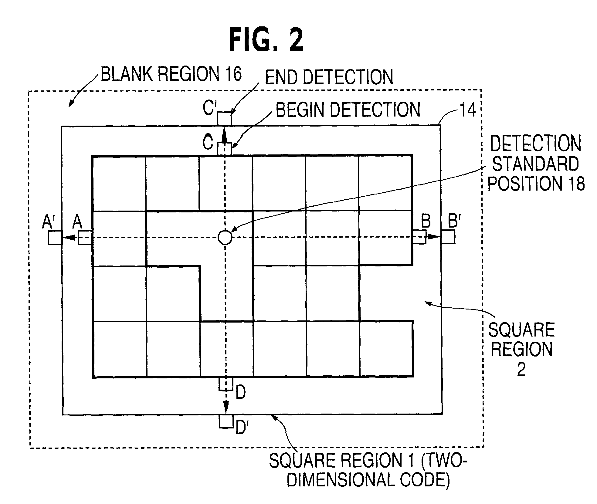
[0104] In S502, the center of the region in which the contiguous block number is Rmax is set as the standard position for the detection of the two-dimensional code region. In FIG. 8, region 3 of FIG. 7 (or region A of FIG. 10) is selected as the region having the maximum contiguous block count, and a circle shown in FIG. 12 is selected as the center of the detected region. Here, the center position shown in FIG. 12 may be the center of the square region bordering on region 3 of FIG. 12.

[0105] In S503, from the detection standard position determined in S502, square blocks are scanned in upward, downward, to the left and to the rig...


PUM


Abstract

An image data is inputted by using a device such as a document scanner. The input image data is scanned in a square block unit of MxN pixels, and blocks that satisfy specific conditions is detected based on the scanning process. In one example, a ratio of white pixels and black pixels falls within scanned blocks is used as the specific condition to detect those blocks. Then a region that neighbored by the other blocks is detected, and is extracted as a two-dimensional code region.

Description

[0001] 1. Field of the invention[0002] The present invention relates to a two-dimensional code extraction method for automatically extracting two-dimensional code images from an image data read into an apparatus such as a computer, using a scanner or other image input device, from sheets upon which the two-dimensional code has been printed on documents or tables.[0003] 2. Description of the Related Art[0004] In recent years, the development of two-dimensional code, which can hold more information than conventional bar codes, has progressed and begun to be used in practical applications. The use of two-dimensional code makes it possible to print all manner of binary data, including documents, imaging and audio data, on paper surfaces.[0005] Documents imprinted with two-dimensional code can be transmitted via facsimile or distributed as printed matter. The receiving party can then read in the two-dimensional code as image data by using an image scanner, and restore data to its origina...

Claims


Application Information

Patent Timeline
IPC IPC(8): G06K7/14G06T5/00G06T7/40G06K7/10
CPCG06K7/1447G06K7/14
Inventor SAKAI, KENICHIRONODA, TSUGIO
Owner FUJITSU LTD
Why Eureka
Try Eureka