Vapor-compression refrigerant cycle for vehicle

Inactive Publication Date: 2002-05-09
DENSO CORP +1
View PDF0 Cites 16 Cited by
  • Summary
  • Abstract
  • Description
  • Claims
  • Application Information

AI Technical Summary

Problems solved by technology

Therefore, in an engine having a relatively small displacement, when the vehicle accelerates or is traveling on an uphill

Method used


Image

  • Vapor-compression refrigerant cycle for vehicle
  • Vapor-compression refrigerant cycle for vehicle
  • Vapor-compression refrigerant cycle for vehicle

Examples


Embodiment Construction

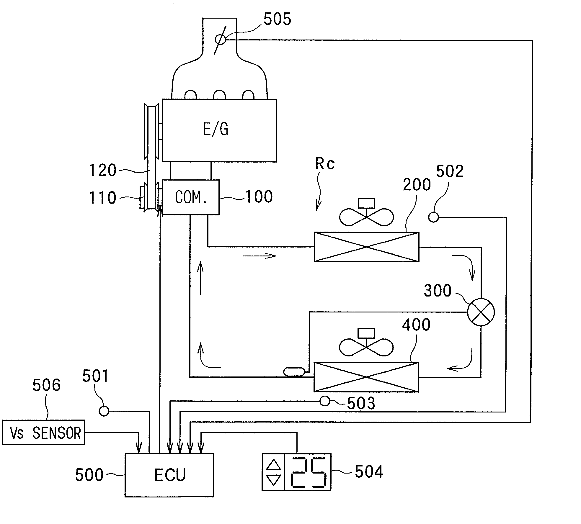
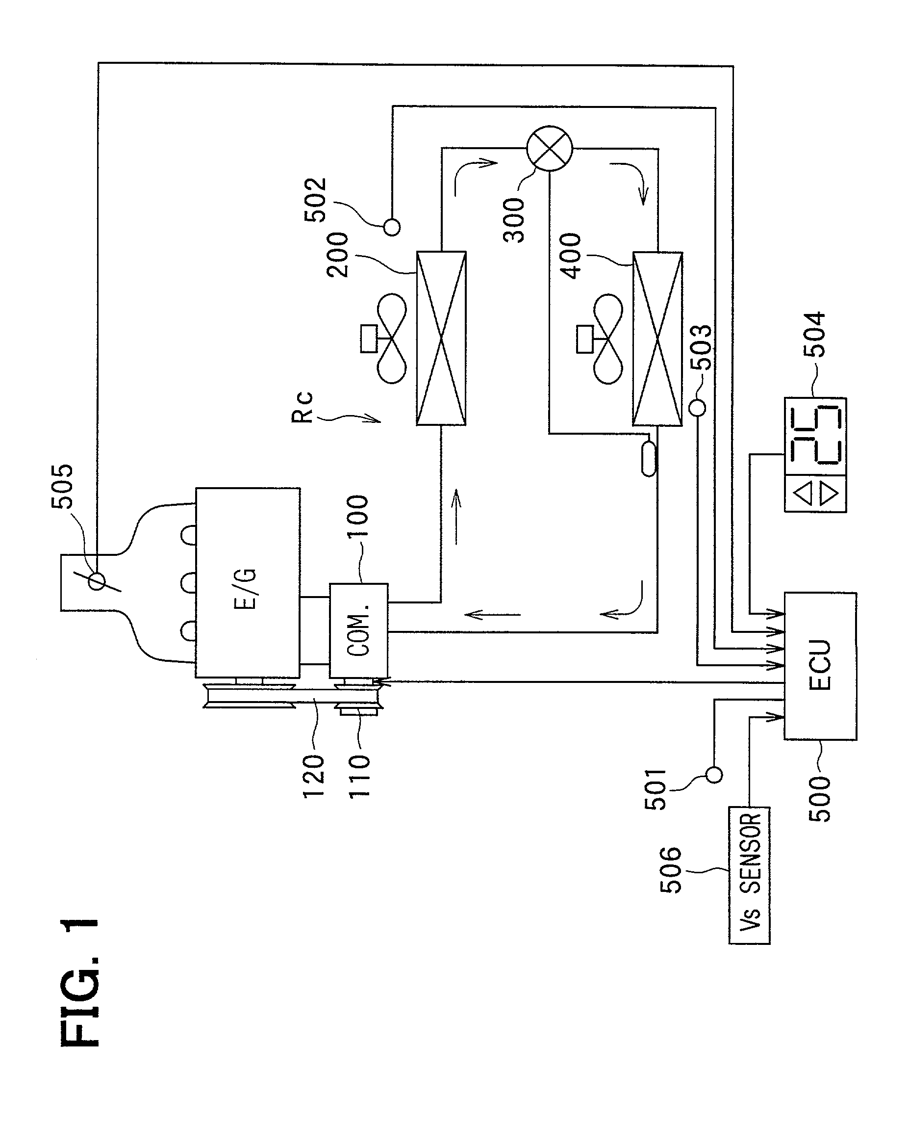
[0022] A preferred embodiment of the present invention will be described hereinafter with reference to the accompanying drawings. In this embodiment, a refrigerant cycle of the present invention is typically used for a vehicle air conditioner.

[0023] As shown in FIG. 1, in a refrigerant cycle Rc, a compressor 100 is driven by an engine (E / G) for travelling a vehicle, to suck and compress refrigerant. The compressor 100 is connected to the vehicle engine E / G through an electromagnetic clutch 110 and a V-belt 120. The electromagnetic clutch 110 is disposed to interrupt a power transmission from the engine E / G to the compressor 100.

[0024] A condenser 200 is disposed to perform a heat exchange between refrigerant discharged from the compressor 100 and outside air. Therefore, refrigerant discharged from the compressor 100 is cooled and condensed in the condenser 200 by outside air. A decompression unit 300 is disposed so that refrigerant discharged from the condenser 200 is decompressed i...


PUM

PropertyMeasurementUnit
Angleaaaaaaaaaa
Speedaaaaaaaaaa
Threshold limitaaaaaaaaaa

Abstract

In a refrigerant cycle for a vehicle air conditioner, a compressor is operated by a power from a vehicle engine, a load detecting unit is disposed to detect load of the engine, an electromagnetic clutch is turned off so that a consumed power consumed in the compressor is reduced to zero when the load detected by the load detecting unit is equal to or larger than a first threshold value. In the refrigerant cycle, the first threshold value is set to be changed along a power-cutting curved line in such a manner that an increase rate of the first threshold value relative to the vehicle speed becomes larger as the vehicle speed becomes larger.

Description

[0001] This application is related to Japanese Patent Application No. 2000-340654 filed on Nov. 8, 2000, the contents of which are hereby incorporated by reference.[0002] 1. Field of the Invention[0003] The present invention relates to a vapor-compression refrigerant cycle for a vehicle, having a compressor which sucks and compresses refrigerant using a power from a driving source (e.g., engine) for travelling the vehicle.[0004] 2. Description of Related Art[0005] In a conventional vehicle air conditioner with a vapor-compression refrigerant cycle, generally, a part of power of an engine for travelling the vehicle is supplied to a compressor through an electromagnetic clutch. Therefore, in an engine having a relatively small displacement, when the vehicle accelerates or is traveling on an uphill road, driveability of the vehicle is deteriorated. Here, the driveability means a vehicle speed change relative to an operation amount of an acceleration pedal.[0006] For example, in JP-B2-3...

Claims


Application Information

Patent Timeline
IPC IPC(8): B60H1/00B60H1/32
CPCB60H1/3208B60H1/00764
Inventor IWANAMI, SHIGEKIUNO, KEIICHIMATSUNO, TAKAYOSHI
Owner DENSO CORP
Why Eureka
Try Eureka