
Access network system

a technology of access network and access network, which is applied in the direction of data switching networks, wireless communication, and assessing restrictions, etc., can solve the problems of extreme deterioration of transmission quality, delay in communication processing for transmission increase, and inability to maintain communication itsel

Inactive Publication Date: 2002-05-09
KDDI CORP +1
View PDF5 Cites 238 Cited by
  • Summary
  • Abstract
  • Description
  • Claims
  • Application Information

AI Technical Summary

Benefits of technology

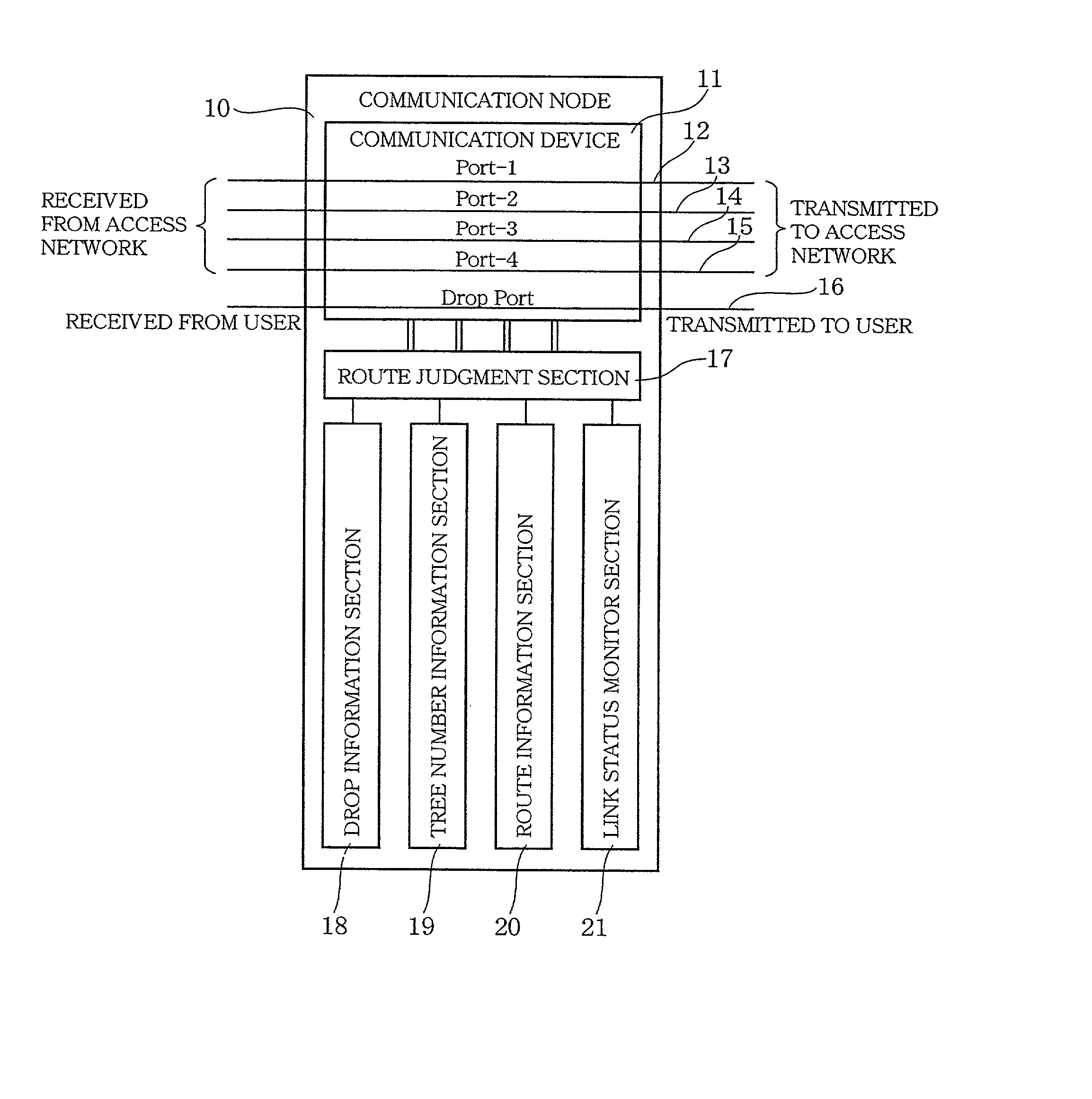
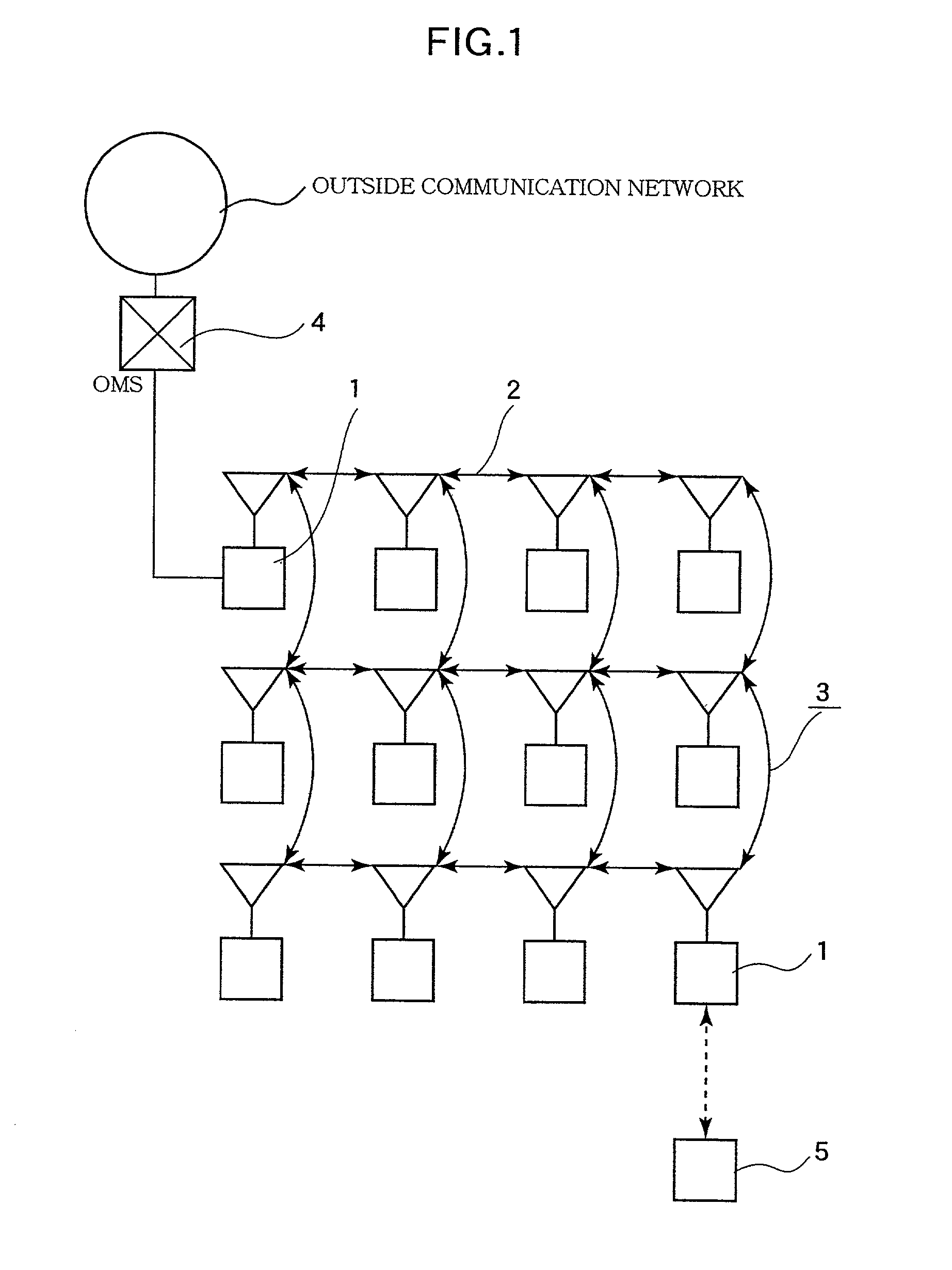
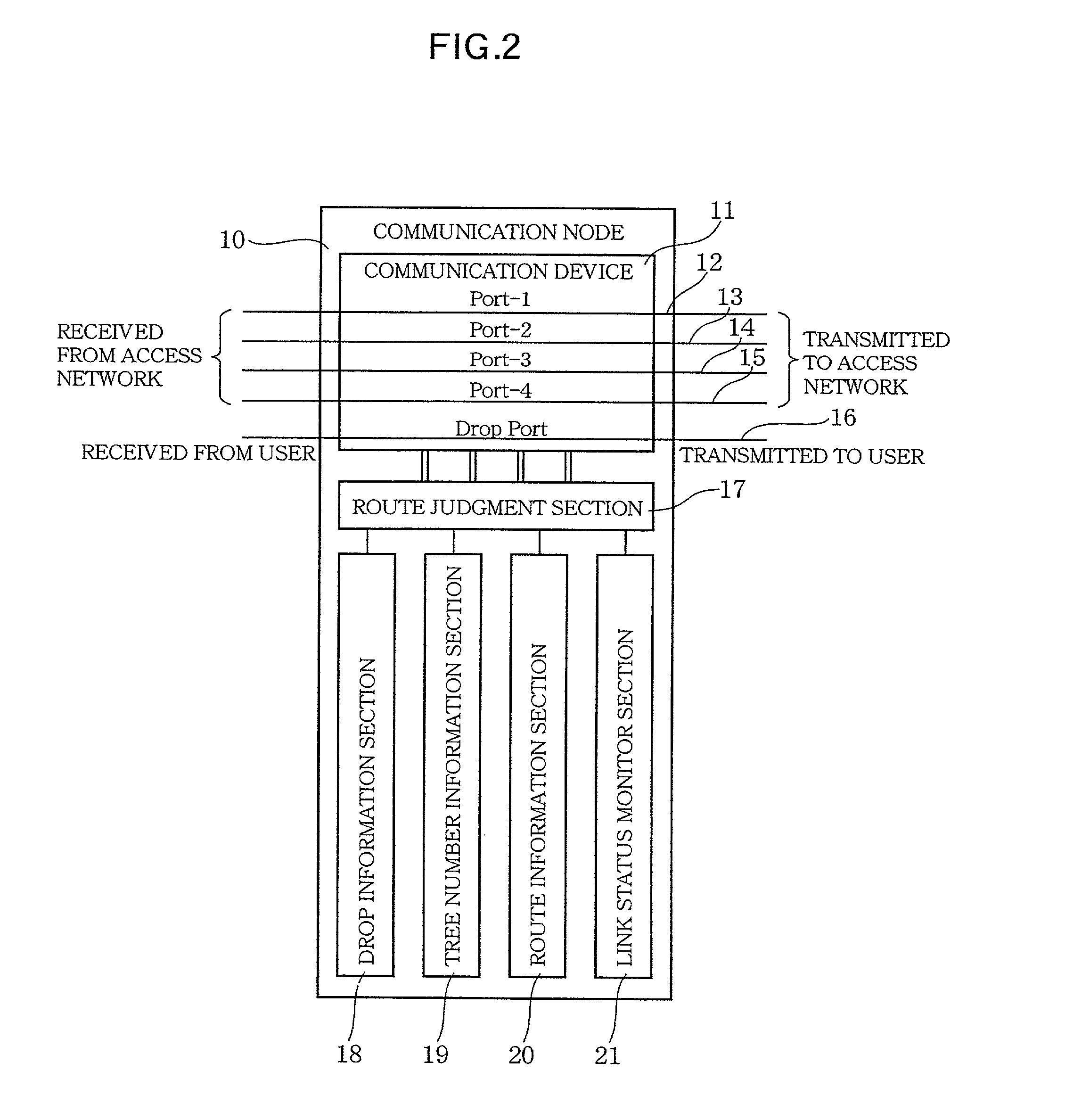
[0033] The communication processing according to the system of the present invention can be realized by a low degree layer of the communication protocol. It is possible to make an instantaneous route switching for link disconnection and the like due to link fault or node fault, and evasion of the fault is possible in a short-term view. Moreover, depending on the operating status of the communication link passages that connect the intervals among the communication nodes of the connection communication passages having a logical tree structure, having a re-structuring method can evade the fault in a long-term view.

Problems solved by technology

In a telecommunication network, when a circuit (link circuit) from a switched network to a base station housing subscribers is constructed with wireless communication as a medium, circuit quality is largely influenced by interference and atmospheric phenomenon and, since the base station located far away from a switchboard requires a base station which relays a wireless circuit due to a problem of range, a delay in communication processing for transmission increases.
Moreover, in the case where the circuit that connects each base station and the switchboard is one route only, if circuit quality fault and communication device fault occur, they lead to extreme deterioration of transmission quality or circuit disconnection so that it is impossible to maintain the communication itself.
However, in the system using the auxiliary circuit, since it is necessary to provide a circuit which is equal to or can be determined to be equal to the current circuit simultaneously with the current circuit being operated, the auxiliary system is not preferable in view of the cost involved in the operation of the network.
While, in the signaling system, in order to cope with a fault, the time that required from detecting the fault to restore the circuit is great.

Method used


Image

  • Access network system
  • Access network system
  • Access network system

Examples


first embodiment

[0072] the present invention will be described below by reference to FIGS. 4, 5, 6, 7, 8, 10, 13, 14 and 16.

[0073] FIG. 10 shows one example of the header transmitted in the network on FIG. 4, which the user data has in possession. Suppose the case where this user data is relayed according to an algorism inside the communication node.

[0074] When the communication node A of FIG. 4 receives the user data via the port #2, FIG. 12 is put into a state of the main process flow (102). This port number received as above is maintained and utilized for subsequent processes. In (103), the destination MN-ID inside the header and the MN-ID of own station are compared. In FIG. 10, the value of the destination MN-ID is [1002], and the value of the MN-ID of own station is [35], [2] from FIG. 8, and it is evident that they do not match each other. Hence, the user data enters the relay process flow (104) from (103).

[0075] In the relay process flow of FIG. 13 (122), the value of the EMS inside the hea...

second embodiment

[0077] A second embodiment of the present invention will be described below by reference to FIGS. 4, 5, 6, 7, 8, 11, 13, 14, 15 and 16.

[0078] FIG. 11A shows one example of the header transmitted in the network of FIG. 4, which the user data has in possession. Suppose the case where this user data is relayed according to an algorism inside the communication node.

[0079] When the communication node A of FIG. 4 receives that particular user data via the port #2, FIG. 12 is put into a state of the main process flow (102). The port number received as above is maintained and utilized for subsequent processes. In (103), the destination MN-ID inside the header and the MN-ID of own station are compared. In FIG. 10, the value of the destination MN-ID is [1002], and the value of the MN-ID of own station is [35], [2] from FIG. 8, and it is evident that they do not match each other. Hence, the user data enters the relay process flow (104) from (103).

[0080] In the relay process flow of FIG.13 (122...


PUM


Abstract

In order to provide an access network system that has durability against transmission quality deterioration and fault and controls the causes of delay in the communication processing for data transmission, the base stations (communication nodes) are arranged in a plurality of cross-points, and the base stations have a function capable of transmitting and receiving the information of an optical wireless communication type and the like, and are mutually linked with each other by wireless and constitute an access network which is accessible cross-wise from each base station by a wireless communication link passage. This access network is wirelessly connected to other outside communication network by an access network terminating set.

Description

[0001] 1. Field of the Invention[0002] The present invention relates to improvements of an access network system such as a communication network system having a mesh structure utilizing wireless transmission such as free space optical transmission and the like, and more in particular to an algorism suitable for performing a routing for communication fault countermeasure and effective information transmission which communication protocol and each communication node (base station) execute.[0003] 2. Description of the Related Art[0004] In a telecommunication network, when a circuit (link circuit) from a switched network to a base station housing subscribers is constructed with wireless communication as a medium, circuit quality is largely influenced by interference and atmospheric phenomenon and, since the base station located far away from a switchboard requires a base station which relays a wireless circuit due to a problem of range, a delay in communication processing for transmissi...

Claims


Application Information

Patent Timeline
Patent Type & Authority Applications(United States)
IPC IPC(8): H04L12/46H04M3/00H04L12/66H04L45/24H04W24/00H04W28/10H04W48/08H04W72/04H04W74/00H04W84/12H04W88/14H04W92/20
CPCH04W28/10H04W92/20H04W74/00H04W48/08
Inventor MOROHASHI, TOMOOMORI, HIDEKI
Owner KDDI CORP
Learn More