
Process and apparatus for control of NOx in catalytic combustion systems

a technology of combustion system and control apparatus, which is applied in the direction of combustion type, combustion using catalytic material, turbine/propulsion engine ignition, etc., can solve the problems of unpredictability of water introduction into the catalytic system, and no controllers disclosed by bhargava, touchton, miyauchi, meyer or blevens, etc., to reduce energy consumption and eliminate water effects on catalyst coatings , the effect of reducing the effect of energy consumption

Inactive Publication Date: 2002-05-16
KAWASAKI HEAVY IND LTD
View PDF0 Cites 27 Cited by
  • Summary
  • Abstract
  • Description
  • Claims
  • Application Information

AI Technical Summary

Benefits of technology

0035] Waste heat in the gas turbine exhaust, or in the exhaust of a downstream boiler can be recovered and used to convert water into high pressure steam which is then injected into the combustor section for the NO.sub.X control in accord with the principles of the invention. This minimizes energy consumption to evaporate and heat the water with a resulting increase in overall process efficiency. Thus, the water introduction system of the invention also provides a vehicle for efficient recovery and feed-back of heat into the combustion

Problems solved by technology

None of Bhargava, Touchton, Miyauchi, Meyer or Blevens disclose employing controllers for continuous control of NO.sub.X by control of water addition.
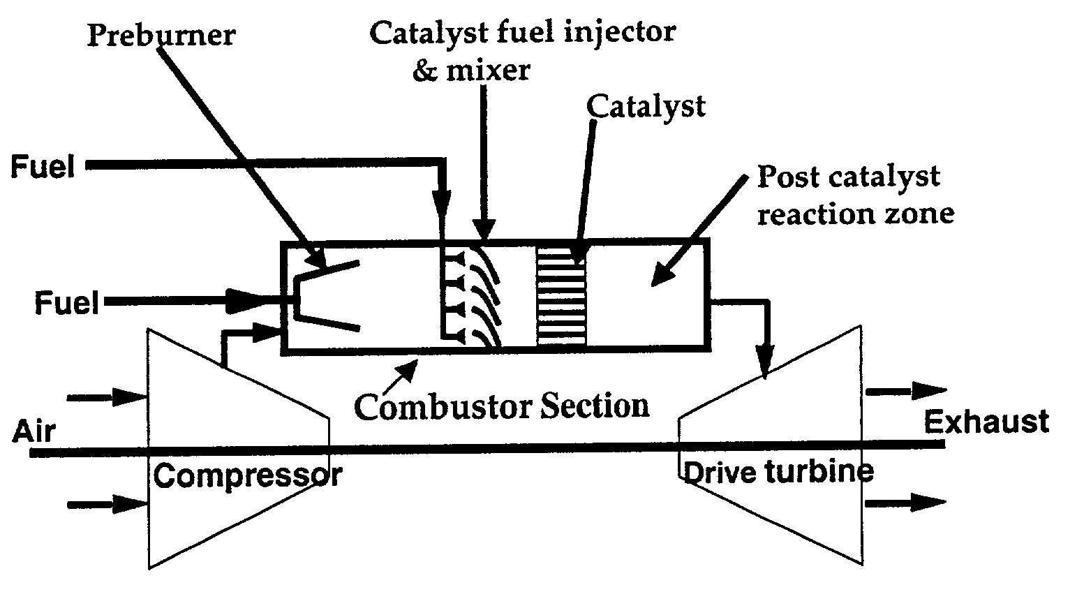
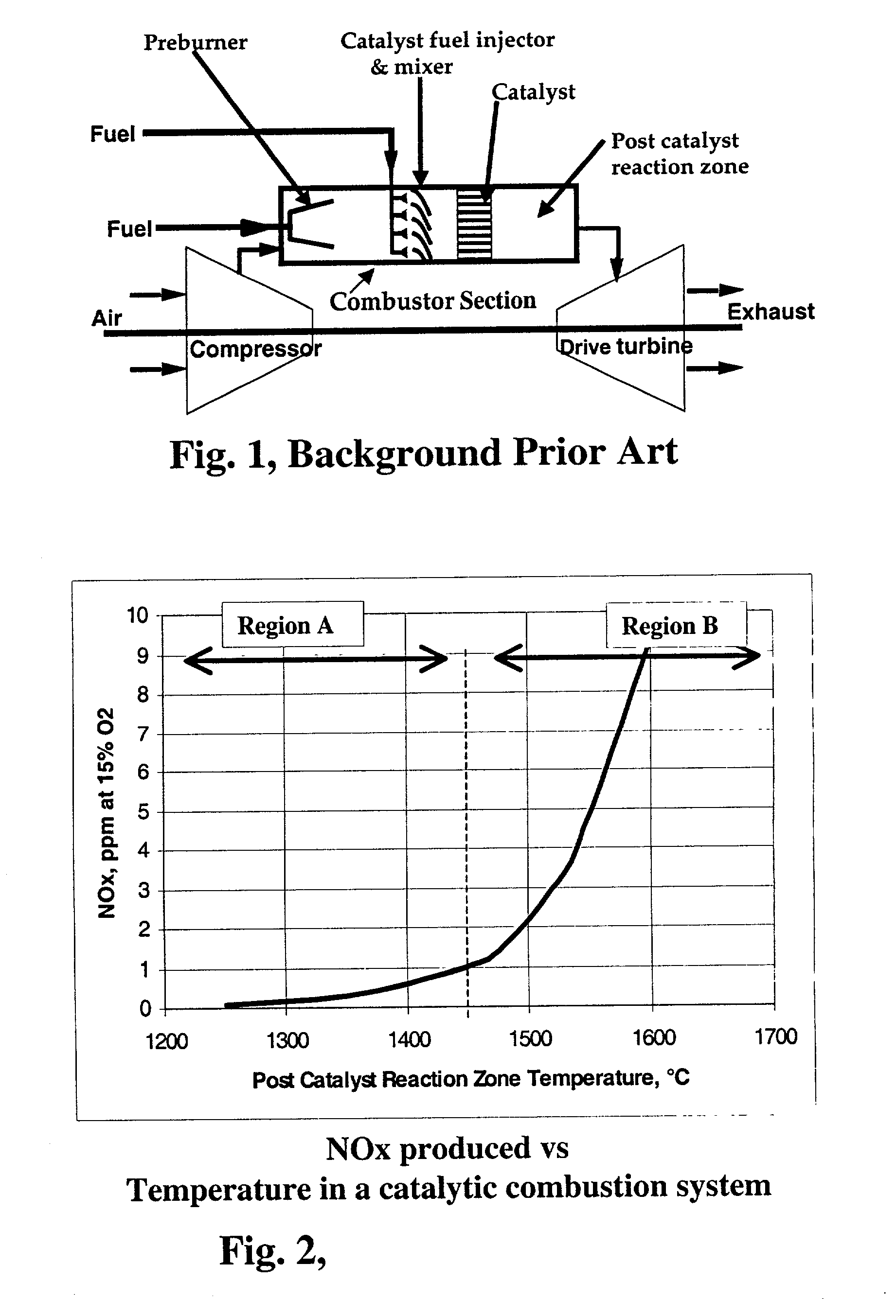
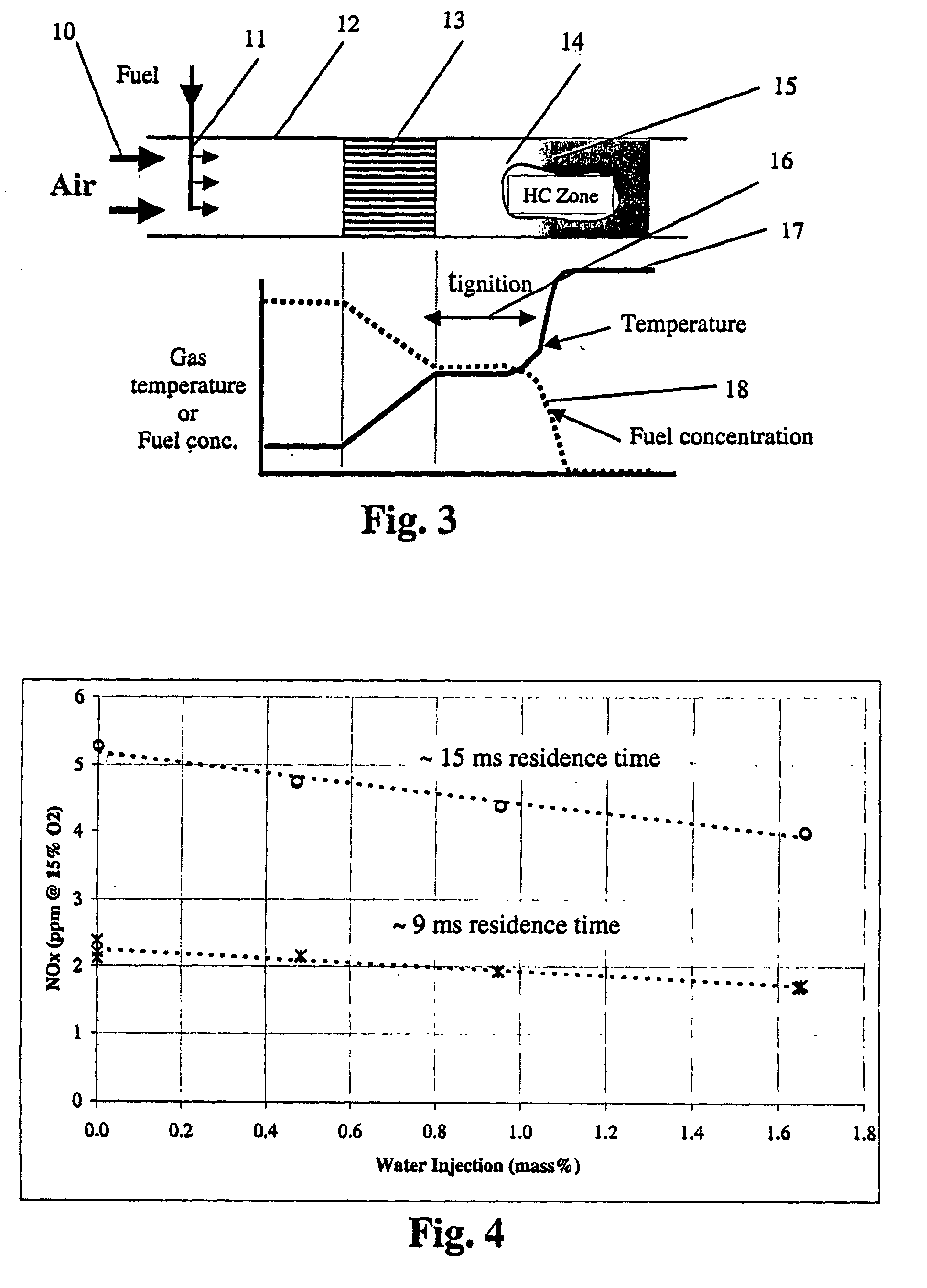
However, flameless catalytic combustion systems are not the same as flame combustors, as is evident from FIG. 3, as a result of which the introduction of water into a catalytic system is not predictable.

Method used


Image

  • Process and apparatus for control of NOx in catalytic combustion systems
  • Process and apparatus for control of NOx in catalytic combustion systems
  • Process and apparatus for control of NOx in catalytic combustion systems

Examples


examples

[0049] A comparative bench-scale test was run without added water and with added water at conditions that are typical of a gas turbine catalytic combustor section. In the series of tests of this Example, a two stage catalyst combustion system was run under typical gas turbine combustor section conditions, namely the conditions for a modern high efficiency turbine at 1515.degree. C. post catalyst reaction zone temperature, a gas pressure of 209 psig and at gas flow rates typical of a gas turbine combustor. Air was heated electrically and then fuel and water was introduced into the air stream at the required level prior to entering the catalyst module. The electrical heat was adjusted to control the gas temperature at the catalyst inlet at the required value. A gas sample was withdrawn downstream of the catalyst and sent to an analytical system to measure NO and NO.sub.2 and reported as a total referred to as NO.sub.X.

[0050] NO.sub.X results are shown in Table 1 below. The following p...


PUM


Abstract

Methods and apparatus for control of NOX in catalytic combustion systems, and more particularly to control of thermal or / and prompt NOX produced during combustion of liquid or gaseous fuels in the combustor sections of catalytic combustor-type gas turbines, by controlled injection of water in liquid or vapor form at selected locations, orientations, amounts, rates, temperatures, phases, forms and manners in the compressor and combustor sections of gas turbines. The ratio of thermal NOX ppm reduction to water addition, in weight %, is on the order of 4-20, with % NOX reduction on the order of up to about 50-80% and NOX of below 2 ppm. Liquid water, steam or superheated steam can be used to reduce NOX in combustion systems operating at reaction zone temperatures above 900° C., preferably 1400° C. to 1700° C. The amount of water added is sufficient to provide a concentration of water in the range of from about 0.1% to about 20% by weight of the total air and fuel mixture flowing into the post catalyst reaction zone. Water is introduced simultaneously or sequentially in a plurality of locations, at selected rates, amounts, temperatures, forms, and purity, preferably in accord with a suitable control algorithm.

Description

CROSS-REFERENCE TO RELATED CASE[0001] This application is the Regular US Application of our earlier-filed Provisional Application of the same title, Ser. No. 60 / 229,576 filed Aug. 31, 2000. This application is also related to copending Ser. No. 09 / ____,____, filed Aug. 29, 2001, by some of us (Yee, Velasco, Nickolas and Dalla Betta), entitled CONTROL STRATEGY FOR FLEXIBLE CATALYTIC COMBUSTION SYSTEM. The benefit of the filing and priority dates of these applications are hereby claimed under 35 U.S.Code, .sctn..sctn. 119 and 120.[0002] The invention relates to methods and apparatus, both devices and systems, for control of NO.sub.X in catalytic combustion systems, and more particularly to control of thermal or / and prompt NO.sub.X produced during combustion of liquid or gaseous fuels in the combustor sections of catalytic combustor-type gas turbines, by controlled injection of water in liquid or vapor form at selected locations, orientations, amounts, rates, temperatures, phases, form...

Claims


Application Information

Patent Timeline
IPC IPC(8): F01K21/04F23C13/00F23D14/68F23L7/00F23R3/40
CPCF01K21/047F23C13/00F23D14/68F23R3/40F23L2900/07008F23L2900/07009F23L7/002
Inventor DALLA BETTA, RALPH A.NICKOLAS, SARENTO G.CARON, TIMOTHY J.MCCARTY, JON G.SPENCER, MARK J.CORR, ROBERT A. II
Owner KAWASAKI HEAVY IND LTD
Learn More