Eureka AIR delivers breakthrough ideas for toughest innovation challenges, trusted by R&D personnel around the world.

Process and device for producing paper reels

Inactive Publication Date: 2002-05-23
VOITH PATENT GMBH
View PDF1 Cites 5 Cited by
  • Summary
  • Abstract
  • Description
  • Claims
  • Application Information

AI Technical Summary

Benefits of technology

[0009] In other words, the paper web exiting the paper machine is immediately guided to a calender in order to calender it. From the exit of the calender, the paper web is guided to the longitudinal cutting and winding device, without intermediate winding, so that the paper reels are produced at the same speed at which the paper machine dispenses the paper web. In this way, the paper web is protected because only one single winding sequence is necessary. Moreover, because it is not necessary that the paper web be intermediately wound onto jumbo reels, considerable set-up times that are necessary for preparing the reel spools and for moving the reel spools and the jumbo reels are omitted. Finally, a large savings in apparatus, e.g., crane arrangements needed for moving the reel spools and jumbo reels, is attained.
[0012] It may be advantageous for the partial webs to be cut in a crosswise manner immediately before being transferred to the winding cores. Thus, essentially same web lengths are wound onto all winding cores, and the winding sequence can begin at the same time for all paper reels.
[0013] It may be advantageous for the winding cores to be pre-accelerated to the web speed before the transfer. In this way, when the partial webs cut from the paper web come into contact with the winding core, they can be attached thereto without any large problems because there is no longer any relative speed between the partial webs and the winding cores.
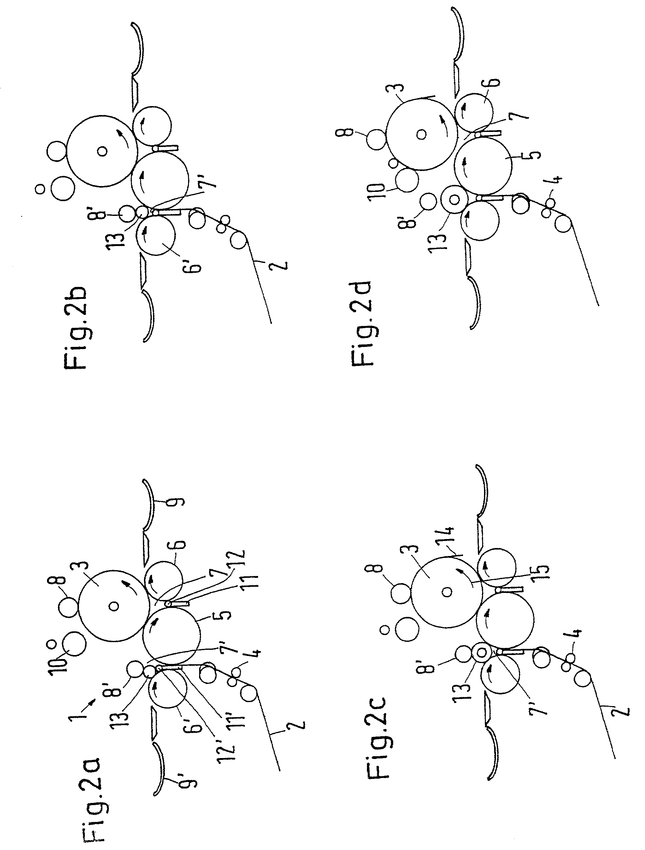
[0016] It may further be advantageous for both winding beds to have one king roll in common, with the completed paper reel being lifted by this king roll and allowed to exit on the other king roll of the winding bed while the paper reels are being wound in the other winding bed. This process achieves several advantages, e.g., the progression of the paper web is essentially kept constant independently of the winding bed in which the paper reels are being wound, and the speed control of the first king roll can achieve the fact that this king roll always runs with the same circumferential speed at which the paper web approaches. Because the complete paper reels are lifted from this first king roll and are allowed to exit on the second king roll, it is also possible to use the first king roll for winding the next batch of paper reels without this being impeded by completed reels. Therefore, the spatial arrangement of the two winding beds in close proximity to one another does not constitute a reason for interrupting the winding process such that the paper web can continue to be processed at the same speed at which it exits the paper machine.
[0019] Preferably, a movable cutting device is arranged behind the calender, which is used for cutting a narrow strip from the paper web, which is to be passed through the calender in its full width. The strip can then be guided into the winding device, which the remaining part of the paper web can be disposed of. For example, it can be guided to a pulper, which reprocesses the paper web waste and supplies it to the paper machine in the form of pulp. The insertion of a narrow strip of the paper web into the winding device is far simpler than the insertion of a wide paper web.
[0021] Preferably, the movable cutting device and the opening mechanism may be interlocked. Thus, it is not possible to move the knives of the longitudinal cutting device together as long as the movable cutting device has not yet cut the paper web in its full width. This prevents uncontrollable conditions from occurring in which the beginning of a partial web may not arrive correctly in the winding device.

Problems solved by technology

It has been observed that the insertion of the paper web in its full width into the calender, the longitudinal cutting device, and the winding device is almost impossible.
However, damage to the paper web could lead to web tears, which are undesirable.
Thus, it is not possible to move the knives of the longitudinal cutting device together as long as the movable cutting device has not yet cut the paper web in its full width.

Method used


Image

  • Process and device for producing paper reels
  • Process and device for producing paper reels
  • Process and device for producing paper reels

Examples


Embodiment Construction

[0043] The particulars shown herein are by way of example and for purposes of illustrative discussion of the embodiments of the present invention only and are presented in the cause of providing what is believed to be the most useful and readily understood description of the principles and conceptual aspects of the present invention. In this regard, no attempt is made to show structural details of the present invention in more detail than is necessary for the fundamental understanding of the present invention, the description taken with the drawings making apparent to those skilled in the art how the several forms of the present invention may be embodied in practice.

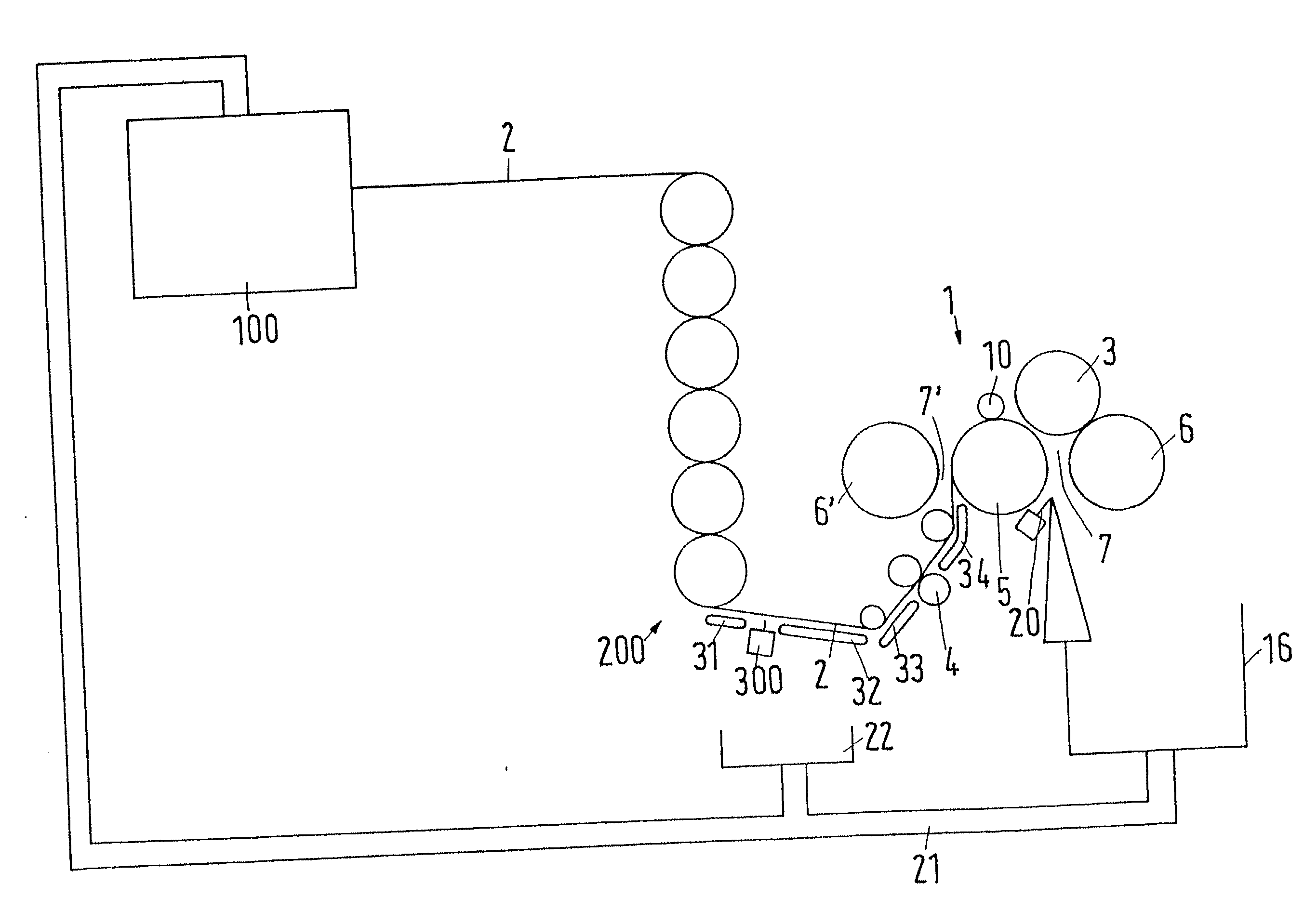
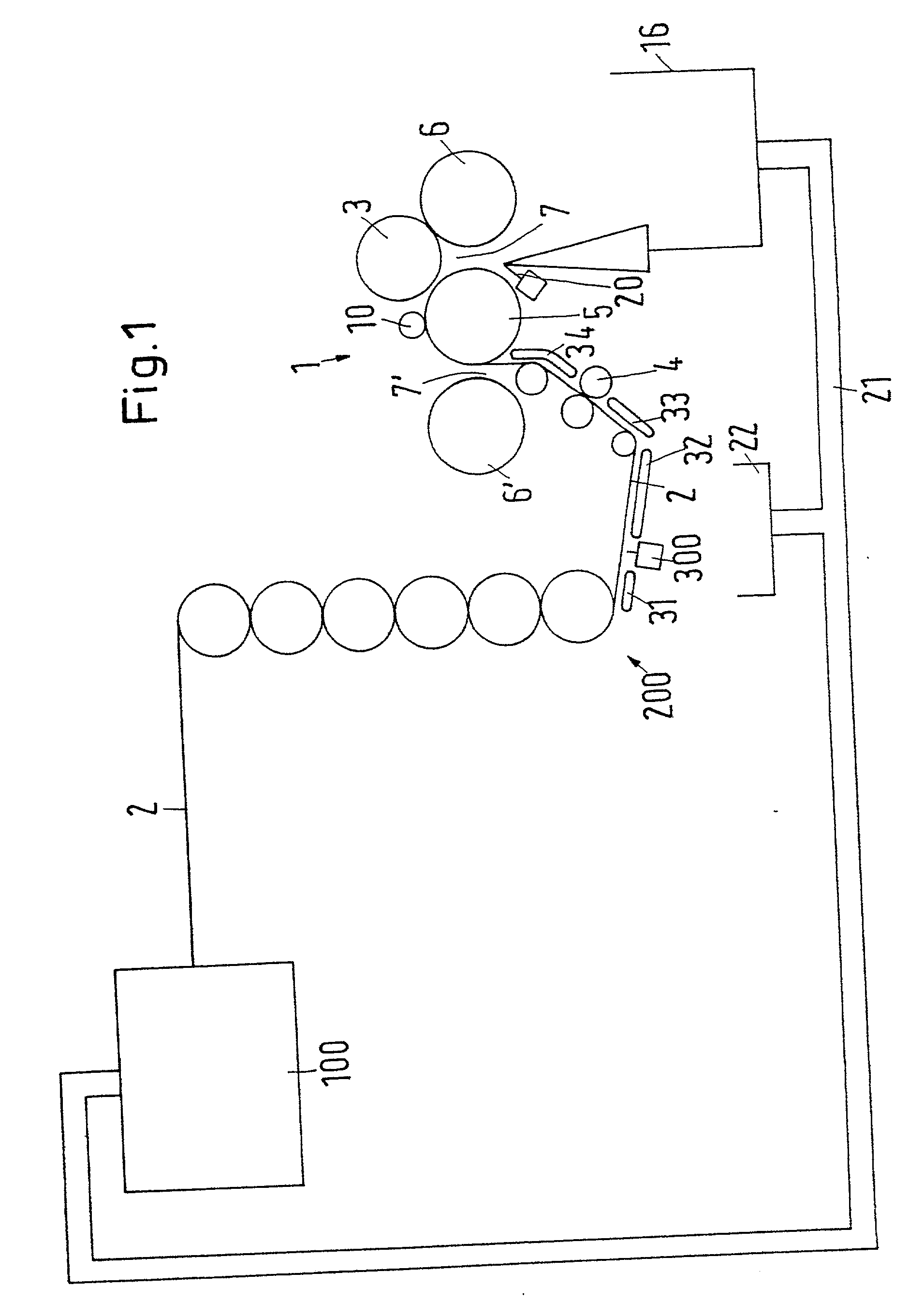
[0044] FIG. 1 shows a schematic depiction of a device for producing paper reels 3 that are finally wound from a paper web 2 in a winding device 1. The paper web 2 is produced in a paper machine 100, which is shown only schematically, in a manner that is known per se and then calendered in a calender 200. Behind the calen...


PUM

PropertyMeasurementUnit
Timeaaaaaaaaaa
Speedaaaaaaaaaa
Widthaaaaaaaaaa

Abstract

Process and apparatus for producing paper reels from a paper web. The process includes calendering the paper web, longitudinally cutting the paper web into partial webs, and winding the partial webs into paper reels. The calendering, longitudinal cutting, and winding occur on-line and without intermediate winding. The apparatus includes a paper machine, a calender, a longitudinal cutting device, and a reel winding device. The paper machine, the calender, the longitudinal cutting device, and the reel winding device are successively arranged in a web run direction.

Description

[0001] The present application claims priority under 35 U.S.C. .sctn. 119 of German Patent Application No. 100 39 040.4, filed on Aug. 10, 2000, the disclosure of which is expressly incorporated by reference herein in its entirety.[0002] 1. Field of the Invention[0003] The invention relates to a process for producing paper reels from a paper web in which the paper web is calendered and cut lengthwise into partial webs and the partial webs are wound into paper reels. The invention further relates to a device for producing paper reels having a paper machine, a calender, a longitudinal cutting device, and a reel winding device.[0004] 2. Discussion of Background Information[0005] The production of paper is known per se. In the paper machine, pulp is poured onto a circulating wire through which the water can drain. At the end of the wire, the paper web being formed is transferred to a drying section that allows a base paper to be removed at the exit of the paper machine. In most cases, t...

Claims


Application Information

Patent Timeline
IPC IPC(8): B65H18/20D21G1/00D21G9/00
CPCB65H18/20B65H2301/41414D21G9/0072B65H2301/41487D21G1/00B65H2301/4148
Inventor CONRAD, HANS-ROLFCRAMER, DIRK
Owner VOITH PATENT GMBH
Why Eureka
Eureka Blog
Learn More