Apparatus and method for the mounting, deployment and use of hydrographic surveying devices

a technology for hydrographic surveys and devices, applied in the direction of transducer details, instruments, seismicity for water-covered areas, etc., can solve the problems of compromising the ability of the transducer to produce a clear and useable signal, the type of survey devices found in the prior art is rather large and complex devices that are not easily deployed or stowed, and achieves the effect of facilitating the movement of the transducer

Inactive Publication Date: 2002-06-06
CARNEY THOMAS
View PDF0 Cites 15 Cited by
  • Summary
  • Abstract
  • Description
  • Claims
  • Application Information

AI Technical Summary

Benefits of technology

0013] To facilitate movement of the transducer, the front or prow of the vessel may be cut back to form a straight or barge like prow. In another embodiment, the boom may be simply mounted upon the main forward deck of the vessel such that the vessel's hull does not have to be modified to form a slot.

Problems solved by technology

This results in the disadvantage that the transducer is subjected to noise from the boat's engine and the turbulent movement of water around and against the hull of the boat.
Since the transducer may be using a sonar arrangement involving emission and reception of sounds as the essential measuring tool, undesirable noise interference compromises the ability of the transducer to produce a clear and useable signal.
In addition to the foregoing, survey devices of the type found in the prior art are rather large complex devices that are not easily deployed or stowed.
Consequently, these devices, and the vessels with which they are used, can not be easily moved from site to site.
Certainly, trailering the vessel together with the survey device is not a viable option.
This prevents the use of the vessel and survey device on inland lakes and waterways as they can not be transported to the site.

Method used


Image

  • Apparatus and method for the mounting, deployment and use of hydrographic surveying devices
  • Apparatus and method for the mounting, deployment and use of hydrographic surveying devices
  • Apparatus and method for the mounting, deployment and use of hydrographic surveying devices

Examples


Embodiment Construction

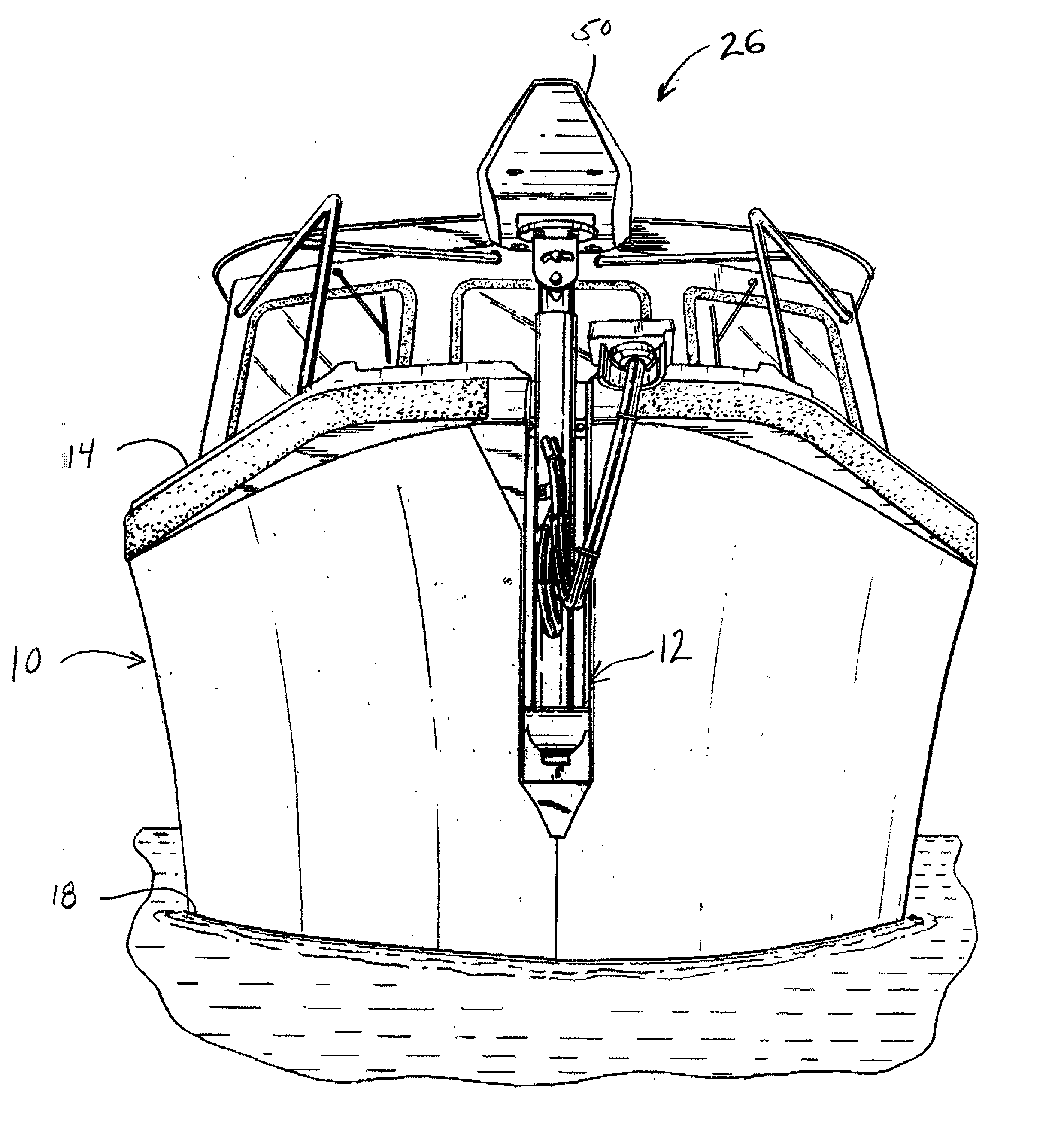
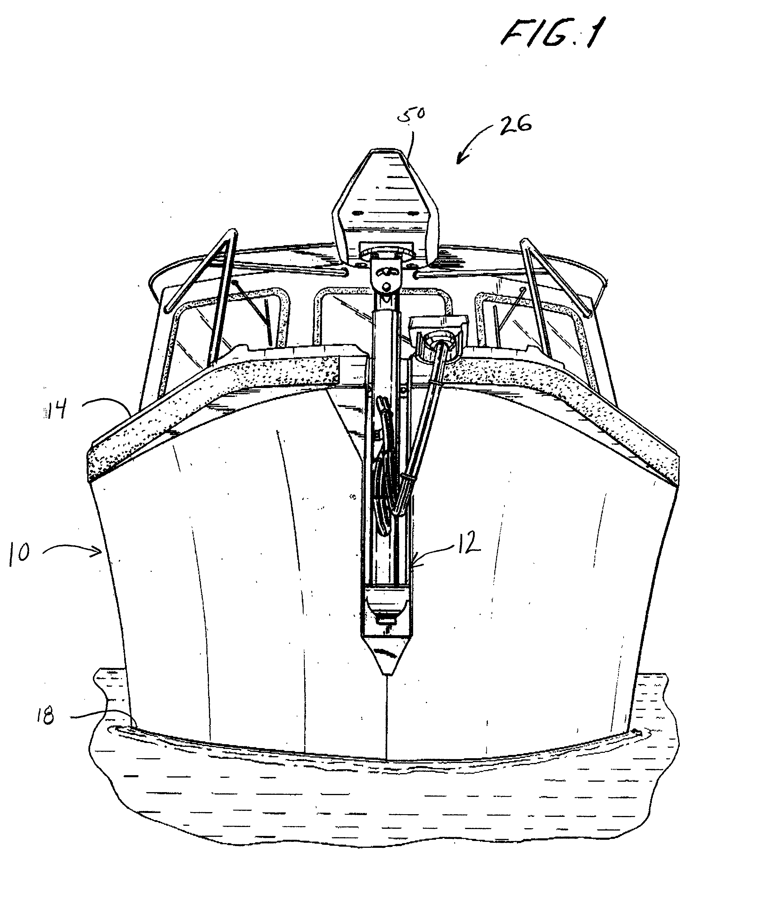
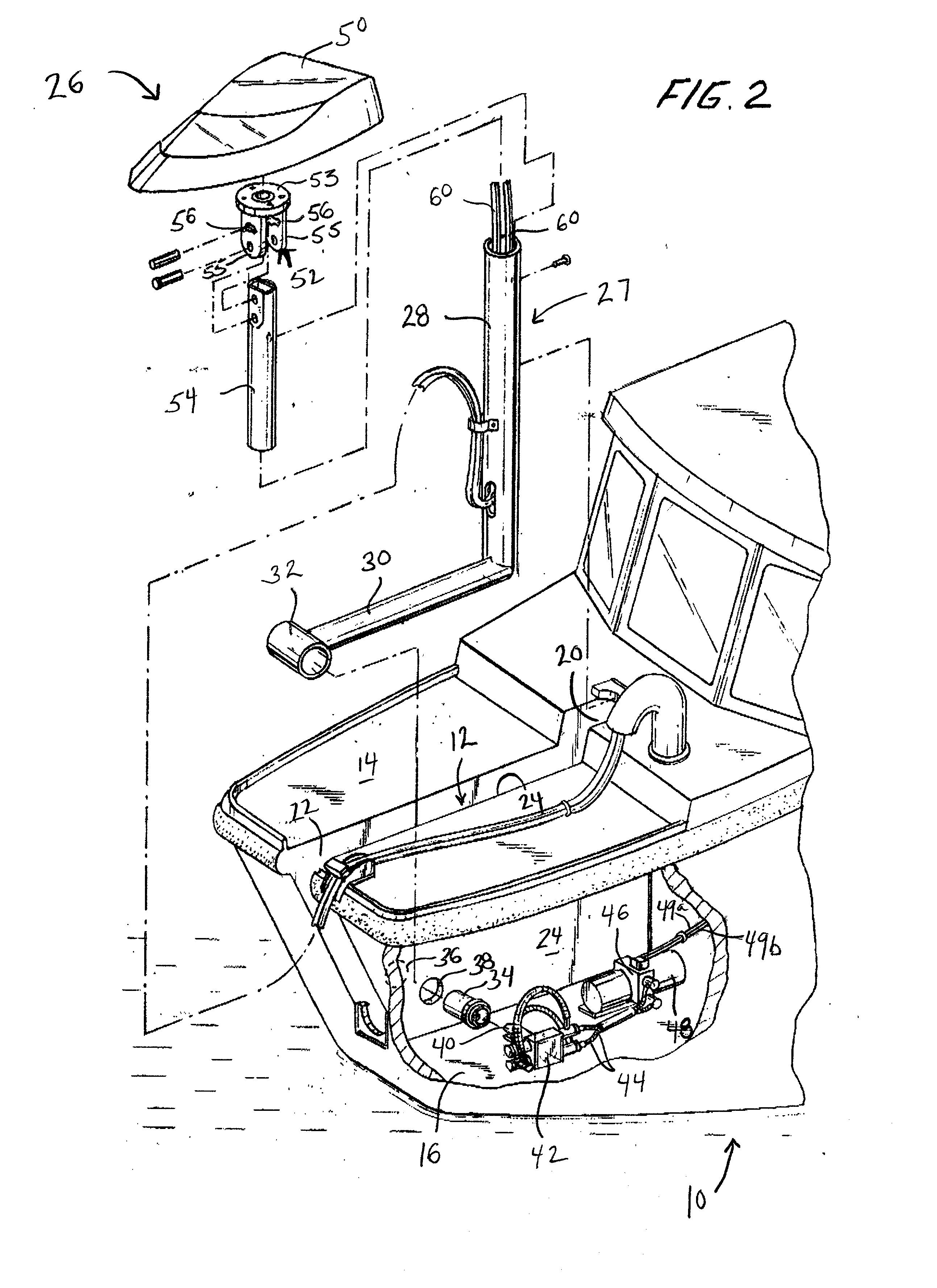
[0021] As seen in FIGS. 1 and 2, a survey vessel generally depicted by the numeral 10, is provide with a slot 12 extending vertically from the top deck 14 downwardly and terminating at the main deck 16, well above the normal high waterline 18. The slot 12 extends rearwardly from the prow along the vertical central plane of the boat and terminates in aft, starboard and port bulkheads, 20, 22 and 24 respectively. The bulkheads are sealed to each other and to the main deck 16 by welding, caulking or the like so as to maintain the integrity of the slot and the boat water tight. It preferable that the survey vessel 10 be approximately twenty to approximately forty-five feet in length so as to permit the easy trailering of the vessel from one survey site to another. Of course, it will be appreciated that the survey apparatus as disclosed herein may be used or adapted for use with any sized vessel.

[0022] Located within the slot 12 is a hydrographic survey apparatus generally depicted by th...


PUM


Abstract

A vessel of generally conventional design is provided with a hydrographic survey apparatus in which the transducer of the survey apparatus is mounted on a boom swingable about a substantially horizontal axis between a deployed and stowed position. The boom is located in a slot aligned in a vertical plane along the boat's centerline and extends downward from the boat's top deck. The boom is mounted at one end near the bow of the boat by attachment to a drive shaft extending beam-wise or transversely across the slot. The drive shaft is operated by a hydraulic rotary actuator. The transducer is mounted on the free end of the boom and is swingable about the drive shaft into and out of the water. The transducer is thus selectively movable from a stowed position to a deployed position in front of the vessel where it is placed in still non-turbulent water, i.e.; water that is free from mechanical vibration and noise of the survey boat and aquatic turbulence from the hull.

Description

[0001] The Applicant hereby claims priority of Provisional Application No. 60 / 089,096 filed Jun. 12, 1998.BACKGROUND OF THE INVENTION[0002] The present invention relates to a hydrographic survey apparatus and survey vessel for mapping and surveying the bottom of an ocean, lake or waterway.[0003] In the past marine surveyors employed transducers placed in the water alongside or behind a vessel. The transducers direct a number of streams of energy, such as sonar or other pulsed energy toward the bottom of the water while the bottom is traversed by the vessel. The transducer receives reflected signals from the water bottom, and produces a raw signal that can be translated into processed survey data producing a map of the water bottom, and or the contents of the water. Sometimes such equipment is augmented with a global positioning satellite (GPS) navigation aid to provide the transducer with the accurate data.[0004] Until now the transducer has been hung over the side of a survey vesse...

Claims


Application Information

Patent Timeline
Patent Type & Authority Applications(United States)
IPC IPC(8): G01S7/521G01S15/89G01V1/38
CPCG01V1/38G01S15/89G01S7/521
Inventor CARNEY, THOMAS
Owner CARNEY THOMAS
Why Eureka
Try Eureka