
Method and apparatus of event-driven based refresh for high performance memory controller

a memory controller, event-driven technology, applied in the field of memory controllers, can solve the problems of performance degradation, unavoidable memory refresh requirement, and not all cells are read or written within the refresh time limi

Inactive Publication Date: 2002-06-06
SILICON INTEGRATED SYSTEMS
View PDF0 Cites 28 Cited by
  • Summary
  • Abstract
  • Description
  • Claims
  • Application Information

AI Technical Summary

Problems solved by technology

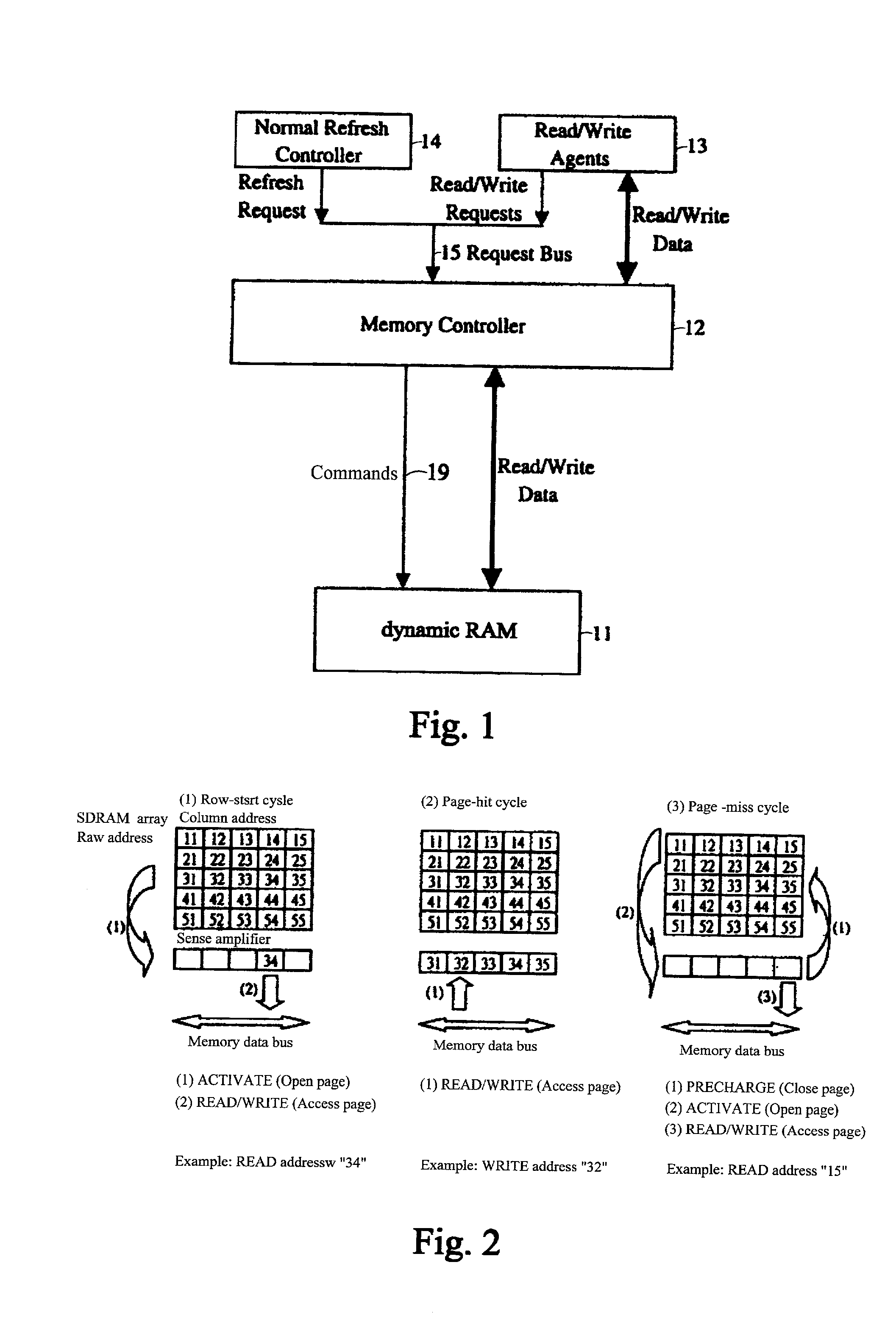
One of the dynamic RAM performance degradation sources is the unavoidable refresh requirement of the memory, since before executing the refresh command, all banks in DRAM must be in the idle state.
Unfortunately, not all cells are read or written within the refresh time-limit.
Thus refresh may interrupt access requests to dynamic RAM 11.
Accordingly, it degrades the memory performance.

Method used


Image

  • Method and apparatus of event-driven based refresh for high performance memory controller
  • Method and apparatus of event-driven based refresh for high performance memory controller
  • Method and apparatus of event-driven based refresh for high performance memory controller

Examples


first embodiment

[0025] [First Embodiment]

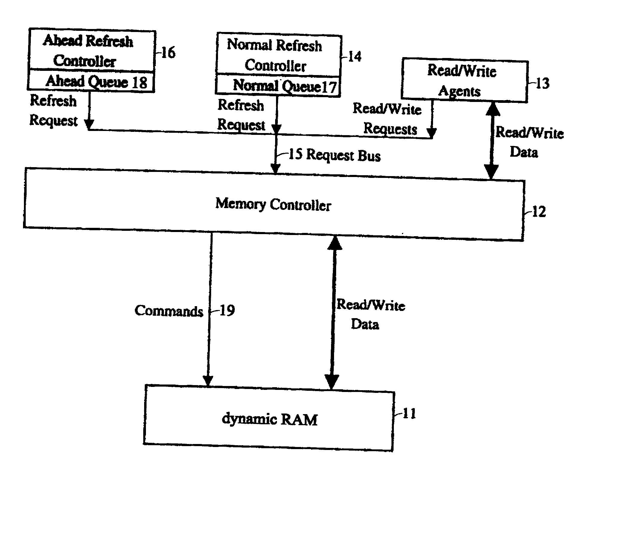
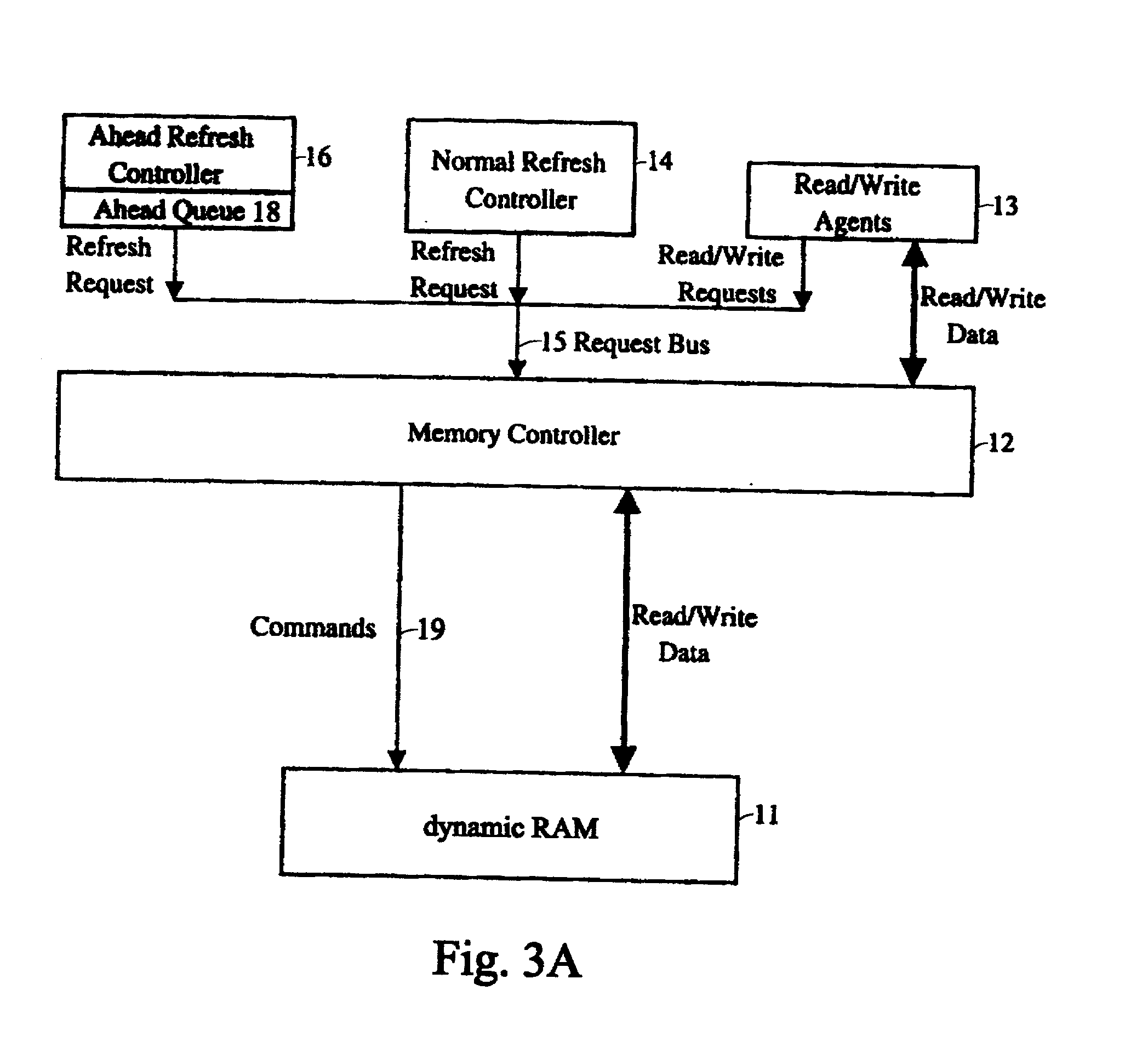
[0026] The control flow of the embodiment according to the present invention is illustrated with reference to FIG. 4A and FIG. 4B. After the dynamic RAM being initialized successfully (is not shown), the process of ahead refresh controller 16 and the normal refresh controller 14 follows the flowcharts.

[0027] FIG. 4A shows the control flow of the ahead refresh controller 16 according to the present invention, which illustrates the process for the ahead refresh controller 16 having the ahead queue 18. The control flow includes the following steps:

[0028] Step 401: monitor the request bus 15 and the command bus 19 of the memory by bus monitor to initiate the ahead refresh; if the request bus 15 and the command bus 19 are both idle, jump to step 402, otherwise repeat this step.

[0029] Step 402: examine whether the ahead queue 18 is full; if the ahead queue 18 is full, then jump to step 401, otherwise jump to step 403.

[0030] Step 403: request the memory bus and iss...

second embodiment

[0039] [Second Embodiment]

[0040] In the first embodiment, the normal refresh controller 14 must have the highest request priority to grant the memory bus to issue the normal refresh command when the ahead queue 18 is empty. But in the second embodiment, not only the ahead refresh controller employees the ahead queue 18 but the normal refresh controller 14 also employees a normal queue 17, as shown in FIG. 3B. The normal refresh controller 14 owns the normal bus request priority to grant the memory bus when the normal queue 17 is not full. However, when the normal queue 17 is full, the bus request priority is promoted to the highest priority to grant the memory bus to issue the refresh command. Such that, the normal refresh controller 14 will reduce the interrupts of the memory bus which are being requested by other read / write agents.

[0041] FIG. 5A illustrates the flowchart of the ahead refresh controller 16 of the second embodiment. The difference of the flowchart of the ahead refre...


PUM


Abstract

A method and apparatus for refreshing dynamic memory is provided. The apparatus includes an ahead refresh controller having an ahead queue for refreshing dynamic random access memory (DRAM) when the memory request bus is idle. In such a way that no dynamic RAM bandwidth is wasted. The apparatus also comprises a normal refresh controller having a normal queue. Giving the normal refresh request in the normal priority unless the normal queue is full. The present invention allows the refresh cycles to gather on the basis of events to minimize the overheads. In other words, even when the system is running in peak performance, the normal refresh controller can largely compact the refresh cycles by means of the normal queue to decrease occurrence of interruption.

Description

[0001] A. Field of the Invention[0002] The present invention relates to a memory controller for controlling the refresh of dynamic RAM, which comprise the system memory. More particularly, the present invention relates to an ahead refresh controller, which enhances system memory performance by performing ahead refresh cycles primarily when the request bus and DRAM bus are all idle for a predefined period and in certain condition.[0003] B. Description of the Related Art[0004] First, basic commands issued to DRAM are introduced before the illustration of FIG. 1. They are initial, activate, read, write, pre-charge and refresh command respectively. The initial command including PALL (pre-charge all banks), two refreshes at least and MRS (mode register set) commands, which are use to initialize DRAM and define how the device operates. After initialization, all banks of DRAM are in the idle state. Then an activate command with respect to a specified row in one bank must be issued before a...

Claims


Application Information

Patent Timeline
IPC IPC(8): G06F13/16
CPCG06F13/1636
Inventor LEE, MING-HSIENWU, YI-KANGWEN, CHIH-CHIANG
Owner SILICON INTEGRATED SYSTEMS
Learn More