Low profile combination scrubbing and squeegee device

a squeegee and combination technology, applied in the field of squeegees, can solve the problems of relative tall tools that are not well suited for cleaning windows in tight spaces

Inactive Publication Date: 2002-06-27
BOOTHBY MICHAEL
View PDF9 Cites 65 Cited by
  • Summary
  • Abstract
  • Description
  • Claims
  • Application Information

AI Technical Summary

Benefits of technology

[0011] It is another object of the present invention to provide such a device that is attached to an elongated pole that allows the user to reach and clean windows in tight fitting spaces, such as the rear windows on a truck or canopy.
[0012] These and other objects of the present invention which will become apparent are met by the low profile combination scrubbing and squeegee device disclosed herein comprising a low profile body with a cleaning surface such as a sponge or brush attached to the top surface, and a thin, squeegee blade attached to the front surface that extends downward from the opposite bottom surface. Connected to the body is an articulating elongated pole that enables the user to stand next to the truck and position the body against the glass to be cleaned. The elongated pole includes a long section and a short section with a first pivoting joint located there between that allows the user to adjust the angular position of the short section of the elongated pole with respect to the long section. Disposed between the distal end of the short section and the body is a rotating joint that enables the user to rotate the body 180 degrees around the center axis. During use, the user may rotate the body so that either the cleaning surface or the squeegee blade may be positioned against the glass without adjusting the first pivoting joint. In the preferred embodiment, the rotating joint includes a hollow central pin, two alignment pins, and a biasing means that tightly holds the body on the distal end of the short section. In the first embodiment, a second pivoting joint is disposed between the short section and the rotating joint that allows the user to selectively adjust the angle of the body with respect to the short section. In a second embodiment, the pivoting joint is replaced with at a fixed angle joint so that the cleaning surface or squeegee blade is always oriented at a fixed angle with respect to the short section. Together, the pivoting and rotating joints allow the user to easily and quickly adjust the angle of the elongated pole and the body so that the device may be continuously and completely moved over close fitting windows.

Problems solved by technology

Unfortunately, the combination of a brush and squeegee mounted on opposite sides of a head creates a relatively tall tool that is not well suited for cleaning windows in tight fitting spaces.
Unfortunately, due to the closeness of the windows, typical squeegees are too thick or wide to fit into the space between the windows or manipulated so that the brush or squeegee contacts the entire surfaces of the windows.

Method used


Image

  • Low profile combination scrubbing and squeegee device
  • Low profile combination scrubbing and squeegee device
  • Low profile combination scrubbing and squeegee device

Examples


first embodiment

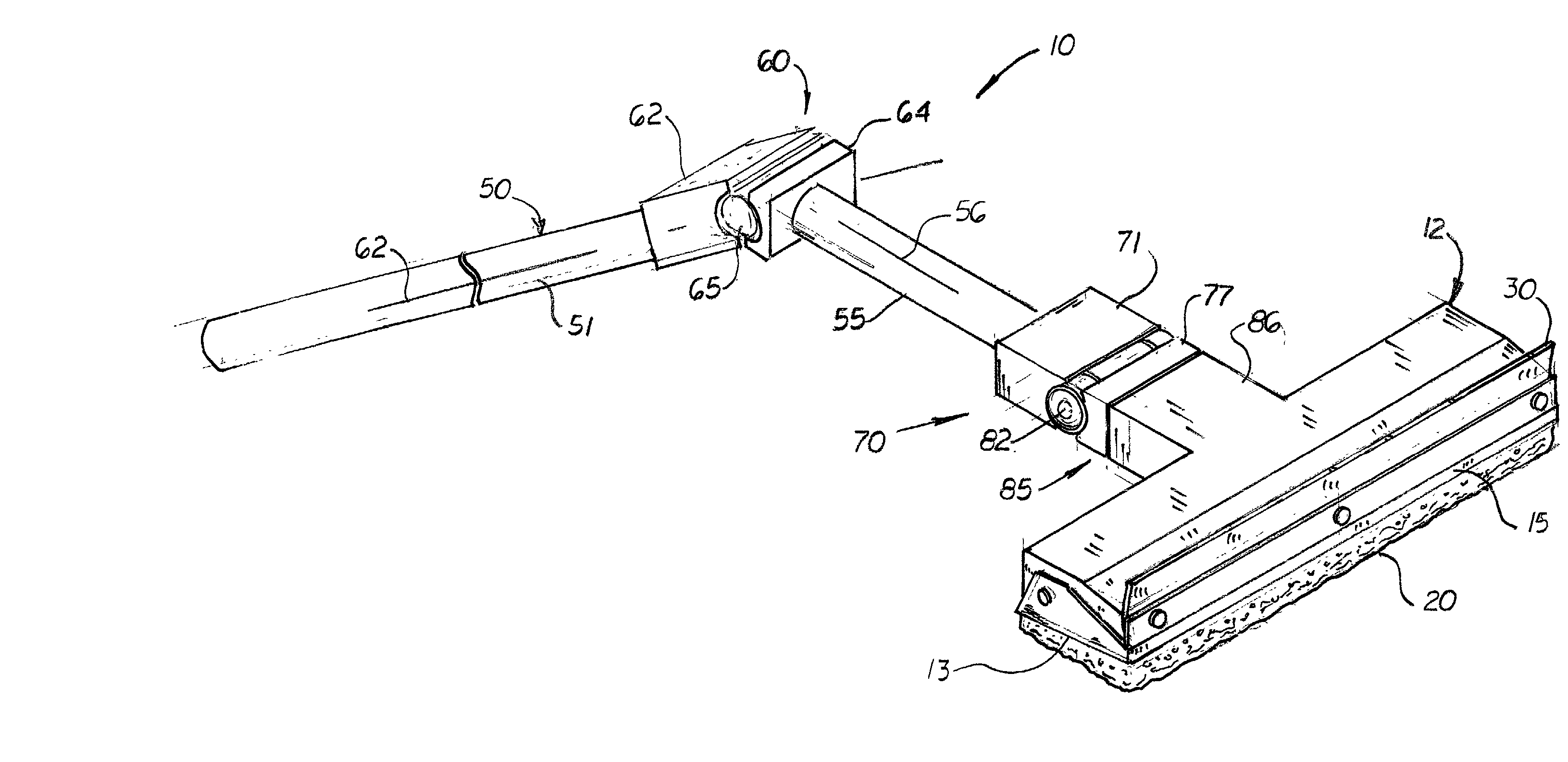
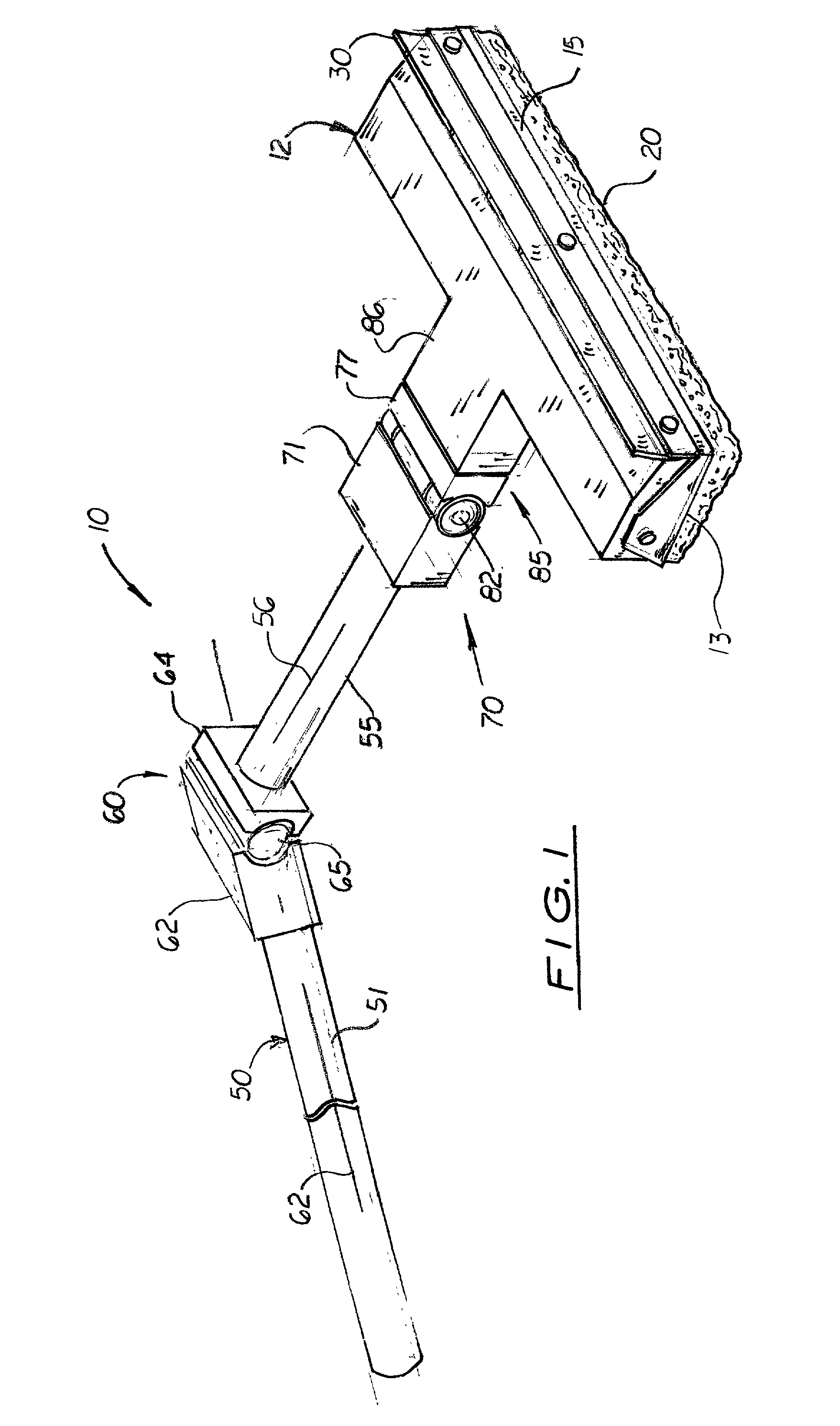
[0031] FIGS. 1-11 show the device, generally denoted as 10, which includes a low profile rectangular-shaped body 12, a sponge 20 attached to one planar surface 13, and a squeegee blade 30 attached to the opposite planar surface or to the front surface 15 (shown). The squeegee blade 30 is designed to extend downward in a direction opposite the sponge 20.

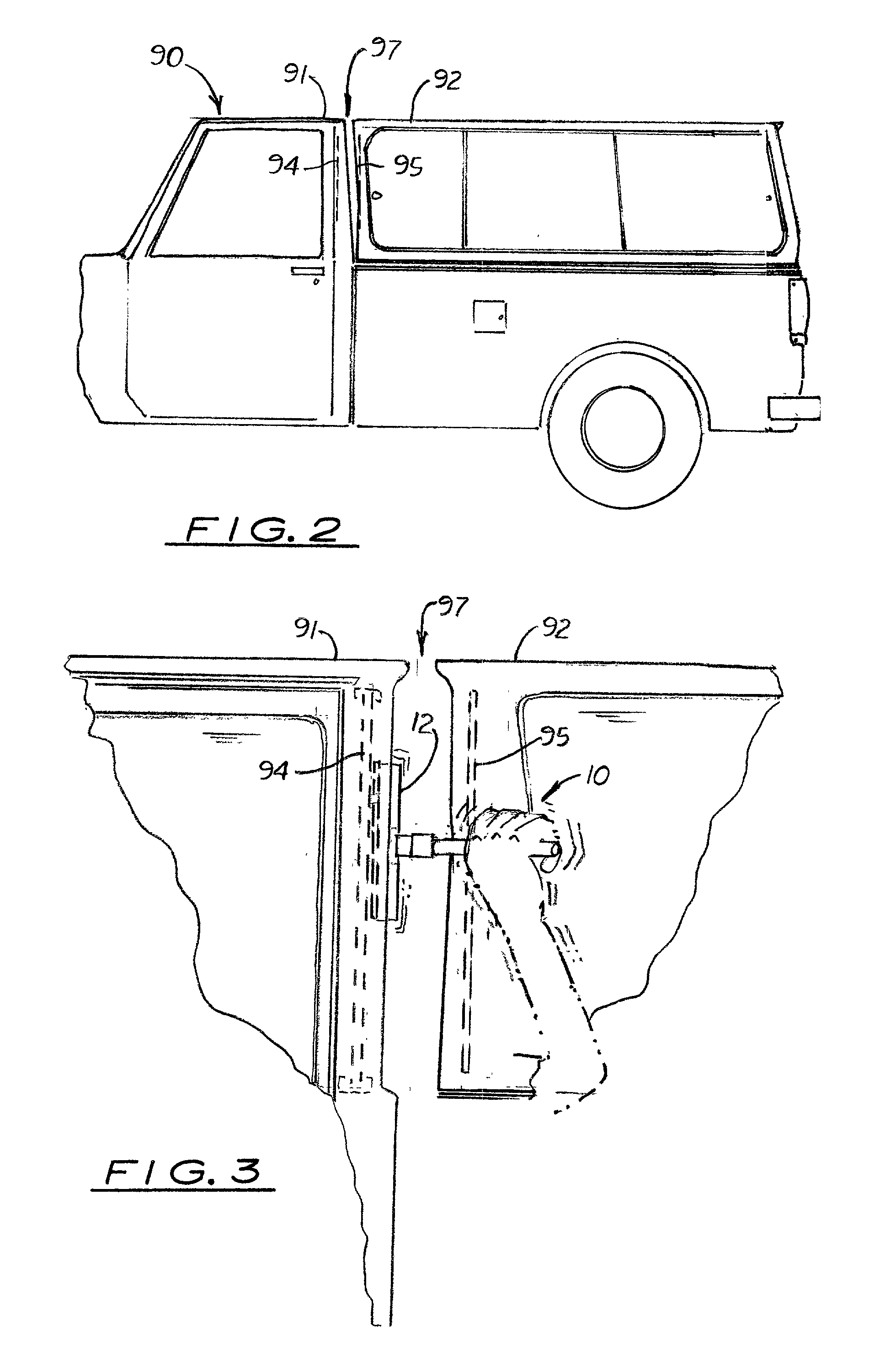
[0032] The device 10 includes articulating elongated pole 50 designed to allow the user to adjusted the orientation of its distal end so it may be easily inserted between the cab and the canopy and position the body 12 against the glass or surface. As shown in FIG. 1, the articulating elongated pole 50 includes a long section 51 and a short section 55. Disposed between the long section 51 and short section 55 is a first pivoting joint 60 that enables the short section 55 to pivot approximately 120 degrees around the long section's transverse axis 52. In the preferred embodiment, the first pivoting joint 60 includes a male and female h...

second embodiment

[0043] The second embodiment may be used with or without the first and second pivoting joints 60, 70 assembled in the elongated pole.

[0044] In the preferred embodiment, the body 12 measures 4 to 6 inches in length, 1 to 11 / 2 inches in width, and {fraction (1 / 2)} to 1 inch in thickness. The long section 51 of the elongated pole 50 measures approximately 48 inches in length and {fraction (1 / 2)} inch in diameter. The short section 55 of the elongated pole 50 measures approximately 6 inches in length, thus making the overall length of the device 10 approximately 56 inches.


PUM


Abstract

A low profile combination brush and scrubbing device used to clean tight fitting, narrow, hard to reach windows on a motor vehicle. The device comprises a low profile body with a cleaning surface, such as a sponge or cleaning pad attached on its top surface, and a rubber blade attached along its front surface that extends downward in a direction opposite the cleaning surface. Connected to the body is an articulating elongated pole. Disposed between the body and the elongated pole is a rotating joint that enables the user to rotate the body 180 degrees around the central axis of the elongated pole. Disposed between the body and the elongated pole are first and second pivoting joints that allow the user to selectively adjust the angular position of the pole and body so that the body may be placed against the surface of both windows. The three joints work together to allow the user to easily adjust the position of the elongated pole on the body so that the device may be used on tight fitting, hard to reach surfaces of a vehicle.

Description

[0001] This is a utility patent application based on a provisional patent application (Serial No. 60 / 258,463) filed on Dec. 27, 2000.[0002] 1. Field of the Invention[0003] This invention pertains to squeegees, and more particularly, to low profile squeegees used to clean surfaces in tight fitting spaces, such as exterior window surfaces on a cab and a canopy of a pickup truck.[0004] 2. Description of the Related Art[0005] Combination brush and squeegee heads attached to an elongated handle are commonly used to clean windows. Typically, the brush and squeegee, mounted on opposite sides of a head, are alternatively moved across the window surface to clean and remove water from the window, respectively. Unfortunately, the combination of a brush and squeegee mounted on opposite sides of a head creates a relatively tall tool that is not well suited for cleaning windows in tight fitting spaces.[0006] In order to clean the exterior rear window on a pickup truck, the individual usually uses...

Claims


Application Information

Patent Timeline
Patent Type & Authority Applications(United States)
IPC IPC(8): A47L1/06A47L13/11A47L13/12B25G1/06
CPCA47L1/06B25G1/06A47L13/12A47L13/11
Inventor BOOTHBY, MICHAEL
Owner BOOTHBY MICHAEL
Why Eureka
Try Eureka