Hooded microwave oven

a hooded microwave oven and hood technology, which is applied in the field of hooded microwave ovens, can solve the problems of unnecessarily passing through, uncontaminated air discharged, and unfavorable air flow in the cavity 2 of the oven, and achieve the effect of smooth airflow in the hooded microwave oven

Inactive Publication Date: 2002-07-04
LG ELECTRONICS INC
View PDF0 Cites 11 Cited by
  • Summary
  • Abstract
  • Description
  • Claims
  • Application Information

AI Technical Summary

Benefits of technology

0022] Therefore, it is an object of the present invention to solve the problems of the prior art...

Problems solved by technology

However, the microwave oven having such structure in the prior art gives rise to problems as follows.
However, even in such case, uncontaminated air discharged forward of the air duct 22 through the right fan 32a also unnecessarily passes through the exhaust filter 22'.
Accordingly, in such case, there is a problem in that the exhaust filter 22' does not fun...

Method used


Image

  • Hooded microwave oven
  • Hooded microwave oven
  • Hooded microwave oven

Examples


Embodiment Construction

[0038] Hereinafter, hooded microwave oven according to the present invention will be explained in detail with reference to a preferred embodiment shown in the accompanying drawings.

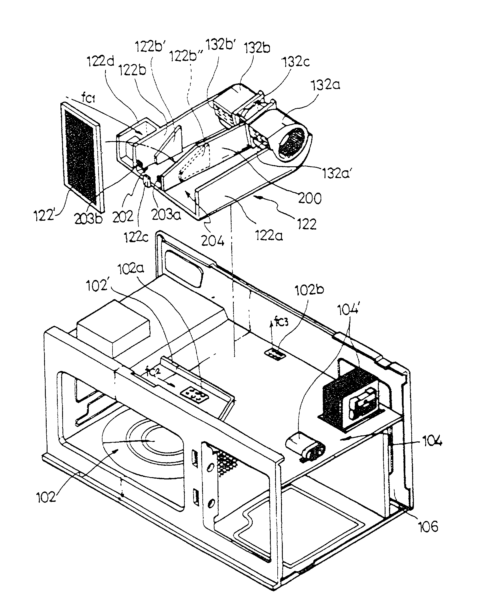
[0039] As shown in FIGS. 3 and 4, a cavity 102 in which a cooking space is provided is formed in one side of the microwave oven. A plurality of passage holes are formed on a top surface of the cavity 102 to form an air inflow portion 102a which allows air to flow into the cooking space and an air outflow portion 102b which allows the air flowed thereinto to flow out.

[0040] In addition, a guide wall 102', which guides the air drawn into an air introduction portion 122d to be described below toward the air inflow portion 102a and partitions the air inflow portion 102a and the air outflow portion 102b, is formed on the top surface of the cavity 102. A bottom surface of an air duct 122 to be described below comes in close contact with the top surface of the guide wall 102'.

[0041] An electric equipment install...


PUM


Abstract

The present invention relates to a microwave oven, and more particularly, to a structure of a microwave oven that has more enhanced operating efficiency and makes less noise by independently forming a flow of air for a hood function and a flow of air for cooling an electric equipment installation chamber and by mounting an exhaust filter only on one side of an air duct. The present invention utilizes a ventilation motor assembly 132 for forming the flow of air for the hood function and the flow of air for cooling the electric equipment installation chamber. In addition, the flow of air discharged from the ventilation motor assembly 132 is forced to flow toward the air duct 122 which has passages divided into a first duct portion 202 and a second duct portion 204. Moreover, among the duct portions 202, 204, an exhaust filter 122' is installed only on the duct portion through which the flow of air for the hood function passes. Furthermore, the electric equipment installation chamber is formed at the relatively upper side of the cavity is 102 so that electric equipments 104' are installed in a position adjacent to the ventilation motor assembly 132. According to the present invention having such structure, the air flows smoothly in the microwave oven, and noise due to the flow of air is minimized.

Description

[0001] The present invention relates to a microwave oven, and more particularly, to a structure of hooded microwave oven in which exhaust and cooling airflow passages are independently formed and an exhaust filter is mounted only in the exhaust airflow passage so as to increase operating efficiency and to reduce flow noise.BACKGROUND OF INVENTION[0002] First, the constitution of a conventional hooded microwave oven will be described in detail with reference to FIG. 1. FIG. 1 is a perspective view of the conventional hooded microwave oven with an outer case thereof removed and an air duct thereof disassembled.[0003] As shown in FIG. 1, a cavity 2 in which cooking is done is formed at one side of the microwave oven. An electric equipment installation chamber 4 is formed at one side of the cavity 2. A plurality of electric equipments 4' are mounted inside the chamber 4. In addition, a blowing fan 8 is mounted on the top of the chamber 4 to form a cooling air stream f.sub.d toward the c...

Claims


Application Information

Patent Timeline
IPC IPC(8): F24C7/02F24C15/20F24F7/06H05B6/64H05B6/80
CPCH05B6/6423F24C7/02
Inventor KIM, SU-HWAN
Owner LG ELECTRONICS INC
Why Eureka
Try Eureka