

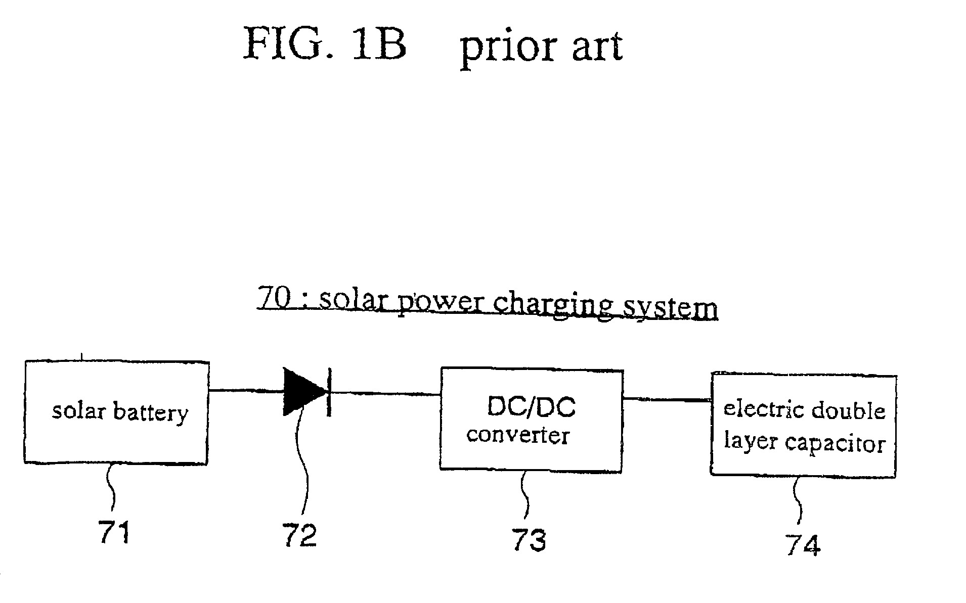
Solar power charging system
a technology of solar energy and charging system, which is applied in the field of solar power charging system, can solve the problems of low efficiency of capacitor charging, inability to meet the maximum power condition of capacitor charging method at the predetermined constant voltage level,
- Summary
- Abstract
- Description
- Claims
- Application Information
AI Technical Summary
Benefits of technology
Problems solved by technology
Method used
Image

Examples
second embodiment
[0064] A second embodiment according to the present invention will be described in detail with reference to the drawings. FIG. 8 is a circuit diagram illustrative of an internal circuit configuration of other voltage converter circuit included in the solar power charging system in a second embodiment in accordance with the present invention The second embodiment is different from the first embodiment only in the circuit configuration of the voltage converter circuit.
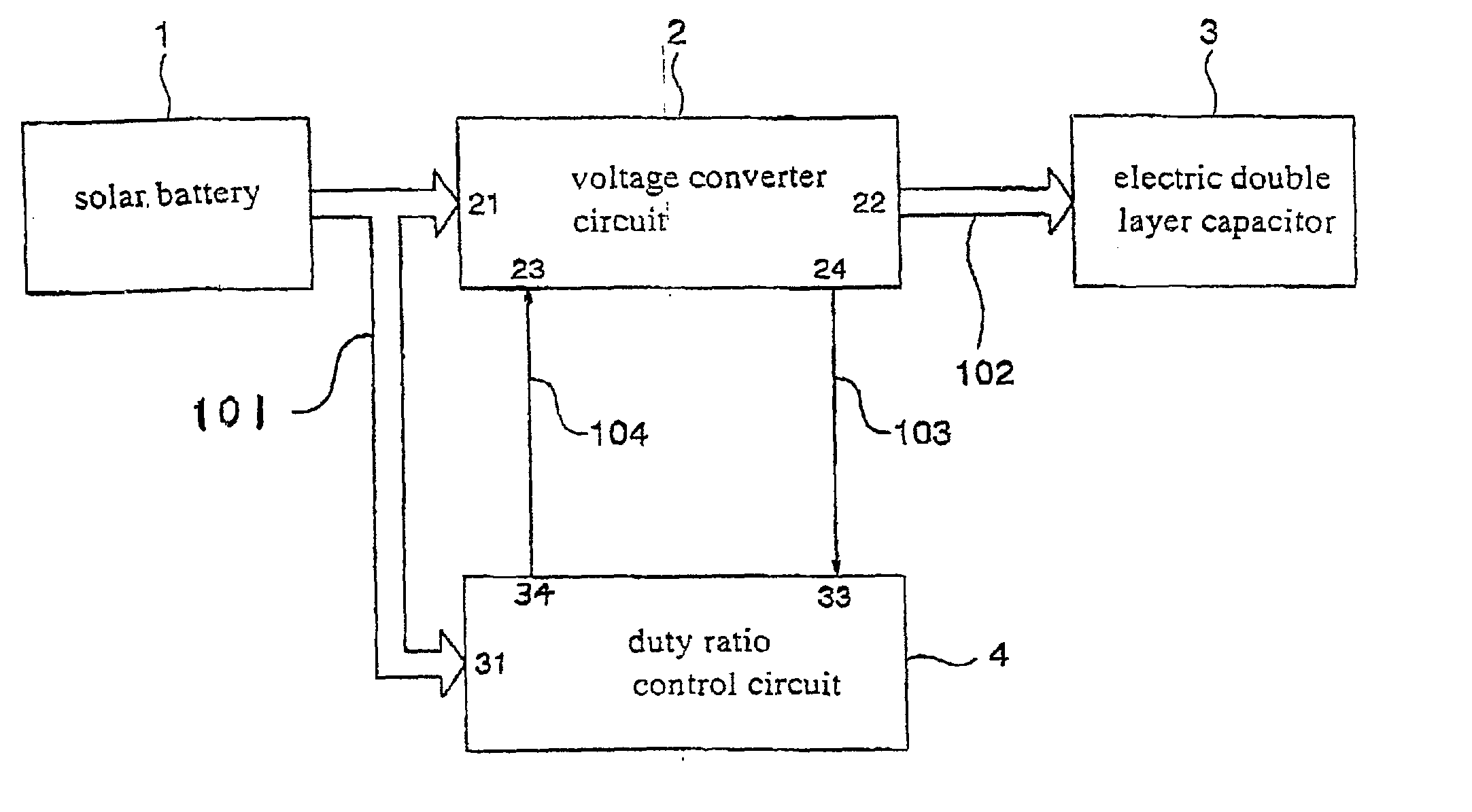
[0065] The voltage converter circuit 2A may comprise a DC chopper circuit of boosting-up-and-down type. The voltage converter circuit 2A has capacitors C1, C2 and C3, inductors L1 and L2, a diode D1, an n-channel transistor Qn1, and a resistance R1. The voltage converter circuit 2A also has the power input terminal 21, the charge voltage output terminal 22, the driving clock input terminal 23, and the detected voltage output terminal 24.
[0066] The power input terminal 21 is connected through the capacitor C1 to a ground....
PUM
| Property | Measurement | Unit |
|---|---|---|
| charging voltage | aaaaa | aaaaa |
| voltage- | aaaaa | aaaaa |
| voltage | aaaaa | aaaaa |
Abstract
Description
Claims
Application Information