Using a master controller to manage threads and resources for scene-based rendering

a master controller and scene-based rendering technology, applied in the field of computer graphics, can solve the problems of increasing the complexity of images displayed, the complexity of graphics processors with a great deal of processing power, and the increase in the amount of data being sent to the display devi

Inactive Publication Date: 2002-07-11
ORACLE INT CORP
View PDF0 Cites 60 Cited by
  • Summary
  • Abstract
  • Description
  • Claims
  • Application Information

AI Technical Summary

Problems solved by technology

Modern graphics systems, however, incorporate graphics processors with a great deal of processing power.
This change is due to the recent increase in both the complexity and amount of data being sent to the display device.
Similarly, the images displayed are now more complex and may involve advanced techniques such as anti-aliasing and texture mapping.
As a result, without considerable processing power in the graphics system, the CPU would spend a great deal of time performing graphics calculations.
This could rob the computer system

Method used


Image

  • Using a master controller to manage threads and resources for scene-based rendering
  • Using a master controller to manage threads and resources for scene-based rendering
  • Using a master controller to manage threads and resources for scene-based rendering

Examples


example embodiment

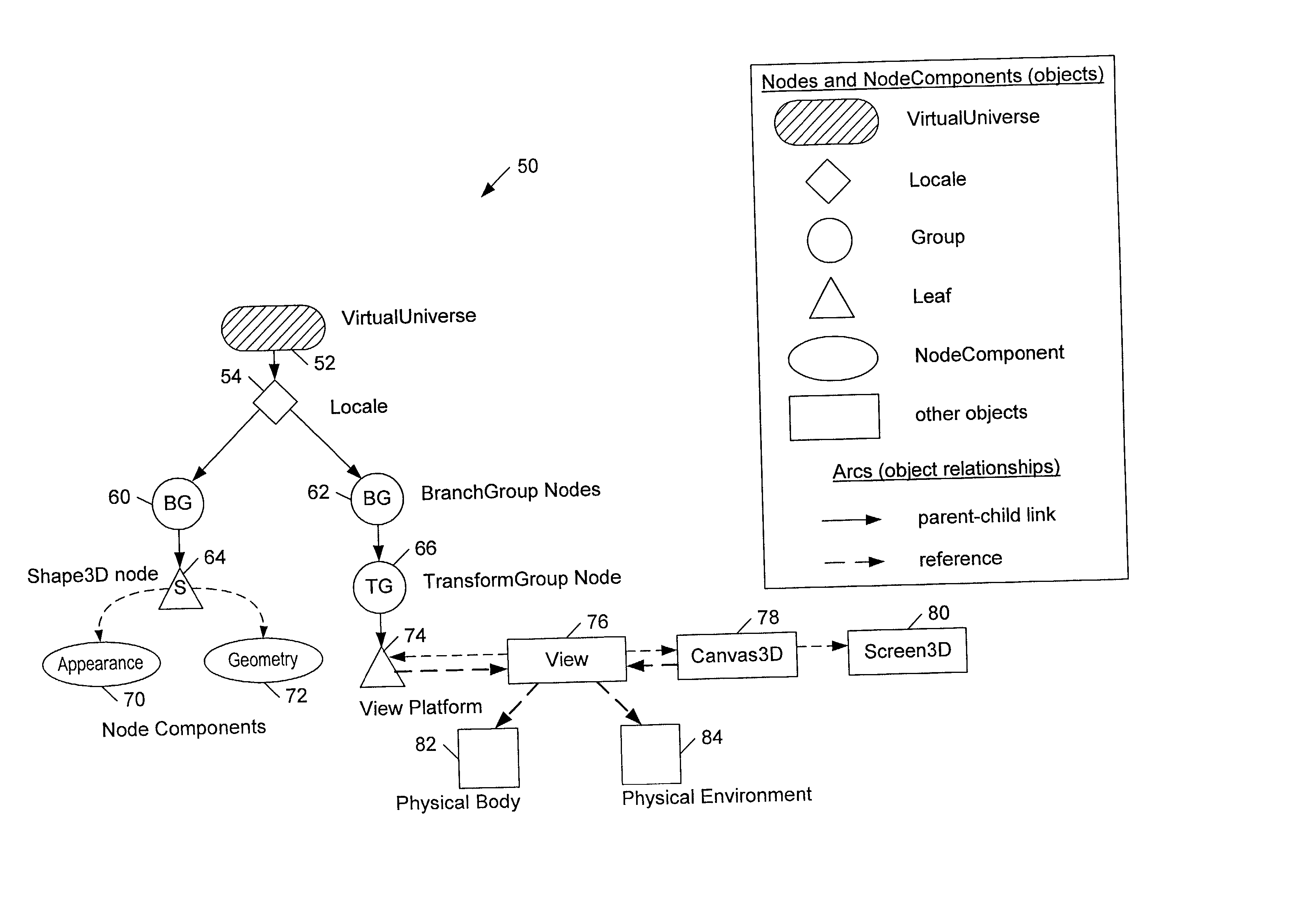
[0070] Example Embodiment Using Java 3D.TM. API

[0071] Java 3D Architecture

[0072] The Java 3D API may be used to implement one embodiment of the system and method described above. One such implementation is described in detail below. However, it is noted that other implementations are also possible and contemplated. To describe this particular embodiment, an overview of the Scene Graph Structure will be presented, and then components of a runtime system will be presented. Next, the process of system startup, runtime system operation, and system shutdown are presented. Then, specific features of this embodiment are explained in greater detail. Also note, that standard Java.TM. and Java 3D variable names, object names, and processes are used herein. For more information on Java and Java 3D, the reader is directed to the books titled "The Java 3D.TM. API Specification," by Sowizral, Rushforth, and Deering, published by Addison-Wesley Publishing Co., ISBN: 0201710412, and "The Java.TM. P...


PUM


Abstract

A system and method for rapid processing of scene-graph-based data and/or programs is disclosed. In one embodiment, the system may be configured to utilize a scene graph directly. In another embodiment, the system may be configured to generate a plurality of structures and threads that manage the data originally received as part of the scene graph. The structures and threads may be configured to convey information about state changes through the use of messaging. The system may include support for messaging between threads, messaging with time and/or event stamps, epochs to ensure consistency, and ancillary structures such as render-bins, geometry structures, and rendering environment structures. A master control thread may be utilized to manage the allocation of resources and the timing of thread execution.

Description

[0001] This application claims the benefit of U.S. Provisional Application No. 60 / 175,580, filed on Jan. 11, 2000.[0002] This application is a continuation-in-part of U.S. application Ser. No. 09 / 668,493 filed on Sep. 22, 2000, which claims the benefit of U.S. Provisional Application No. 60 / 156,054 filed on Sep. 24, 1999.[0003] 1. Field of the Invention[0004] This invention relates generally to the field of computer graphics and, more particularly, to graphics systems and software that manage and render three-dimensional graphics data.[0005] 2. Description of the Related Art[0006] A computer system typically relies upon its graphics system for producing visual output on the computer screen or display device. Early graphics systems were only responsible for taking what the processor produced as output and displaying it on the screen. In essence, they acted as simple translators or interfaces. Modern graphics systems, however, incorporate graphics processors with a great deal of proce...

Claims


Application Information

Patent Timeline
IPC IPC(8): G06T15/00G06T17/00
CPCG06T15/005G06T17/005G06T2210/61
Inventor SOWIZRAL, HENRYRUSHFORTH, KEVINTWILLEAGER, DOUG
Owner ORACLE INT CORP
Why Eureka
Try Eureka