Supercharge Your Innovation With Domain-Expert AI Agents!

Optical position sensor with threshold updated dynamically by interpolation between minimum and maximum levels of output signal

a technology of optical position sensor and threshold, which is applied in the direction of conveyor counting, instruments, pulse technique, etc., can solve the problems of optical sensor unreliability, prone to failure, and moving parts in mechanical switches, etc., and achieves the effect of easy and economical implementation

Inactive Publication Date: 2002-08-01
IBM CORP
View PDF0 Cites 20 Cited by
  • Summary
  • Abstract
  • Description
  • Claims
  • Application Information

AI Technical Summary

Benefits of technology

[0017] A final objective is an approach that can be implemented easily and economically according to the above stated criteria.

Problems solved by technology

As one skilled in the art would readily appreciate, mechanical switches include moving parts and are prone to contact bounce and malfunction due to early life failure of any moving part in the switch.
Optical sensors, which consist of light sources and detectors, are often utilized to overcome these problems, but they are also susceptible to failures caused by problems inherent in the nature of their components.
For example, optical sensors tend to become unreliable as a result of large changes in ambient light, misalignments between the light source and the detector, reduced light levels caused by dirt or debris accumulation, reduced light levels caused by the aging of the internal light sources, and manufacturing differences in sensitivity between devices.
Thus, even though optical sensors are more immune than mechanical switches to mechanical noise and failure, their reliability remains uncertain under normal operating conditions.
In a reflective embodiment of optical-sensor apparatus (not illustrated in the figures), this problem can similarly result from a decrease in the reflectivity of the moving target.
Similar problems can arise when an increase in the light sensed by the detector 14 occurs to the point where the minimum amplitude 26 of the detector output 16 is always higher than the threshold 22, as illustrated in FIG. 5A, This can happen, for example, when the ambient or background light is too high, or when the light source 12 is supplied with too much current that yields a greater than rated light beam B. In a reflective embodiment, this problem can result from an increase in ambient reflectivity.
In view of the foregoing, it is clear that the conventional fixed detection threshold used with prior-art optical sensors is inadequate to provide maintenance-free, reliable, long-term service under variable operating conditions.
Some approaches have been disclosed in U.S. Pat. No. 5,898,170 and U.S. Pat. No. 5,739,524 to improve similar problems, but they are limited to specific optical-sensor applications.

Method used


Image

  • Optical position sensor with threshold updated dynamically by interpolation between minimum and maximum levels of output signal
  • Optical position sensor with threshold updated dynamically by interpolation between minimum and maximum levels of output signal
  • Optical position sensor with threshold updated dynamically by interpolation between minimum and maximum levels of output signal

Examples


Embodiment Construction

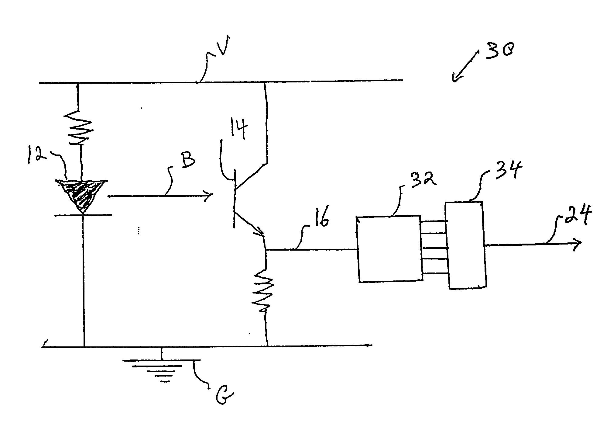
[0038] The heart of this invention lies in the idea of dynamically varying the detection threshold of an optical sensor by judiciously setting it between the extreme values of the analog output of the light detector. This variable threshold compensates for changes in the analog output characteristics of the sensor and guarantees that a two-state condition is preserved in the digital logic output of the optical sensor.

[0039] Referring to the drawings, wherein like parts are designated throughout with like numerals and symbols, FIG. 6 illustrates an ADC embodiment 30 of the invention, wherein the analog output 16 from the light detector 14 of an optical sensor is fed to an analog-to-digital converter 32 to produce a digital binary number that represents the magnitude of the analog signal 16 (voltage or current). This embodiment is preferably used in systems that include a microprocessor that contains the ADC function. Thus, the digital value of the light-detector signal produced by th...


PUM


Abstract

The detection threshold of an optical sensor is dynamically calibrated by measuring the maximum and minimum levels of the analog output produced by the sensor's light detector and setting the detection threshold of the sensor at an intermediate level between the two. The new detection threshold thus established is then used as the voltage reference that determines the logic state of the system. The invention may be implemented using analog-to-digital converter hardware already embedded in the system. Alternatively, the invention may be implemented using digital-to-analog converter hardware that may also be already present in the system.

Description

[0001] 1. Field of the Invention[0002] This invention relates generally to methods and apparatus for sensing the position of a moving part. In particular, the invention relates to a dynamically tracking threshold for maintaining the reliability of an optical sensor.[0003] 2. Description of the Related Art[0004] Position sensors are typically used in machines to monitor the physical state of a moving mechanical component of an automated system. For example, the exact position of a moving part may need to be determined to establish an "on" or "off" control signal for mechanical applications, such as an end stop or travel limit for an X- or Y-motor to move a cartridge gripper of a robotic system loading and unloading magnetic tapes into and from a tape drive or cartridge cell. In such applications, the position sensor determines when the tape cartridge has reached the desired physical location within the tape drive (or the cartridge cell) and the sensor's output is used both to stop th...

Claims


Application Information

Patent Timeline
IPC IPC(8): G01J1/44
CPCG01J1/44
Inventor BUTKA, DAVIDGOODMAN, BRIAN GERARDMCINTOSH, MICHAEL PHILIPYARDY, RAYMOND
Owner IBM CORP
Features
  • R&D
  • Intellectual Property
  • Life Sciences
  • Materials
  • Tech Scout
  • Unparalleled Data Quality
  • Higher Quality Content
  • 60% Fewer Hallucinations
Learn More