

High-gradient high-pump-head screw conveyor device
a conveyor device and screw technology, applied in the direction of transportation and packaging, loading/unloading, packaging, etc., can solve the problems of restricting the efficiency of conveyance, and achieve the effect of efficient lifting operation
- Summary
- Abstract
- Description
- Claims
- Application Information
AI Technical Summary
Benefits of technology
Problems solved by technology
Method used
Image

Examples
first embodiment
[0058] (First Embodiment)
[0059] A first embodiment will be described with reference to FIGS. 1 to 5.
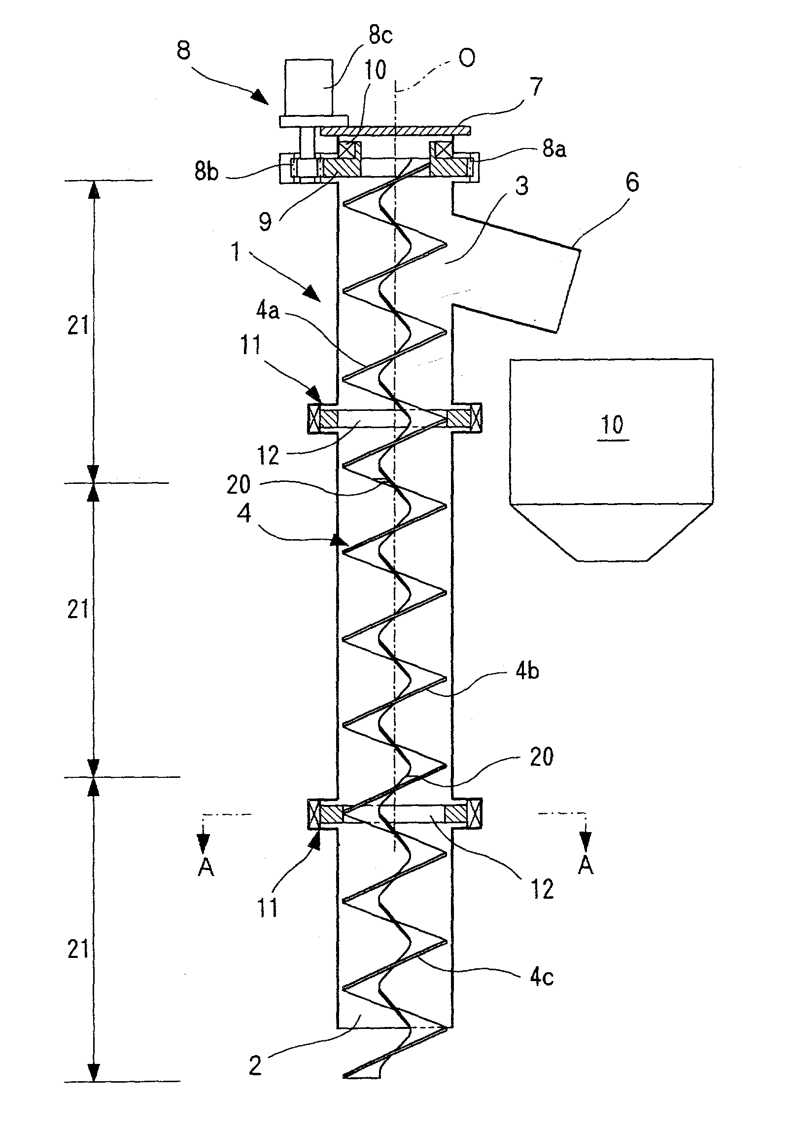
[0060] This screw conveyor conveys sediments (conveyed materials) via a shaft, the sediments having been drilled using, for example, a tunnel excavator on the earth side. As shown in FIG. 1, a cylindrical casing 1 having an inlet 2 at its lower end and a discharge port 3 at its upper end has a ribbon screw 4 provided on the same axis O. The cylindrical casing 1 has a discharge chute 6 mounted at its upper end and connected to the discharge port 3, and a screw rotating device 8 also provided at its upper end to drive the ribbon screw 4 to rotate around the axis O. Reference numeral 10 denotes a loading hopper in which sediments from the discharge chute 6 are loaded.
[0061] Instead of the discharge port 3, an upper end member 7 may be omitted or a discharge port may be formed in the upper end member 7 so that sediments are discharged from the upper end of the cylindrical casing 1.
[0062] ...
second embodiment
[0071] (Second Embodiment)
[0072] A second embodiment will be described with reference to FIG. 10. The second embodiment is constructed so that at least one of the outer peripheral supporting sections 11 of the first embodiment transmits rotational drive force to the ribbon screw 4.
[0073] That is, this embodiment comprises a main screw rotating device 61 having the same construction as the screw rotating device 8 of the first embodiment, and auxiliary screw rotating devices 62 are provided on arbitrary ones of (in the drawing, all) the outer peripheral supporting sections 11.
[0074] In a first specific example of the auxiliary screw rotating device 62, a ring gear 63 is provided on a driving rotation ring (rotation ring) 60 constituting the rotation ring of the outer peripheral supporting section 11. Further, guide pinions 64 are arranged at a plurality of locations instead of the guide rollers, and one of the guide pinions is used as a drive pinion 65, or the drive pinion 65 is provi...
third embodiment
[0095] (Third Embodiment)
[0096] According to a third embodiment, the ribbon screw 4 of the second embodiment has a central shaft 141 disposed in a hollow portion thereof as shown in FIG. 22.
[0097] The central shaft 141, rotatably arranged in the hollow portion of the ribbon screw 4 on the axis O of the casing 1 so as to form a predetermined gap from the ribbon screw 4, has its upper end supported by the upper end of the casing 1 via a central-shaft rotating device 142 and has its lower end supported by a scraping blade (support member) 143 via a bearing 144, the scraping blade 143 attached to the casing 1 to guide conveyed materials (sediments). The central shaft 141 is supported by the upper end member 7 via an inner bearing 142 (?) so as to be rotatable around the axis O, and is rotationally driven by a passive gear 142a of the central-shaft rotating device 142, a drive pinion 142b that meshes with the passive gear 142a, and a central-shaft rotational drive device (hydraulic or el...
PUM
 Abstract
Description
Claims
Application Information