Pneumatic rotary wheel coupling with early wheel bearing wear warning

a technology of pneumatic rotary wheels and early bearing wear, which is applied in the direction of tyre parts, tyre-inflating valves, tyre measurements, etc., can solve the problems of vehicle bearings running dry, reducing their useful life, and air leakage that builds up excessive pressur

Inactive Publication Date: 2002-09-12
COL VEN
View PDF0 Cites 34 Cited by
  • Summary
  • Abstract
  • Description
  • Claims
  • Application Information

AI Technical Summary

Problems solved by technology

However, these systems are prone to air leaks that build up excessive pressure on the wheel's bearing mountings at the end of the vehicle's axle.
This excessive pressure deteriorates the bearing seals and pushes the lubricant grease out of them, dimini

Method used


Image

  • Pneumatic rotary wheel coupling with early wheel bearing wear warning
  • Pneumatic rotary wheel coupling with early wheel bearing wear warning
  • Pneumatic rotary wheel coupling with early wheel bearing wear warning

Examples


Embodiment Construction

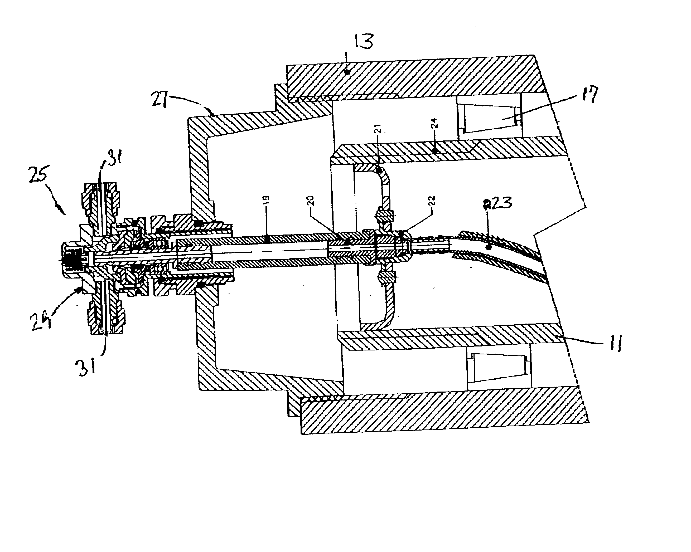
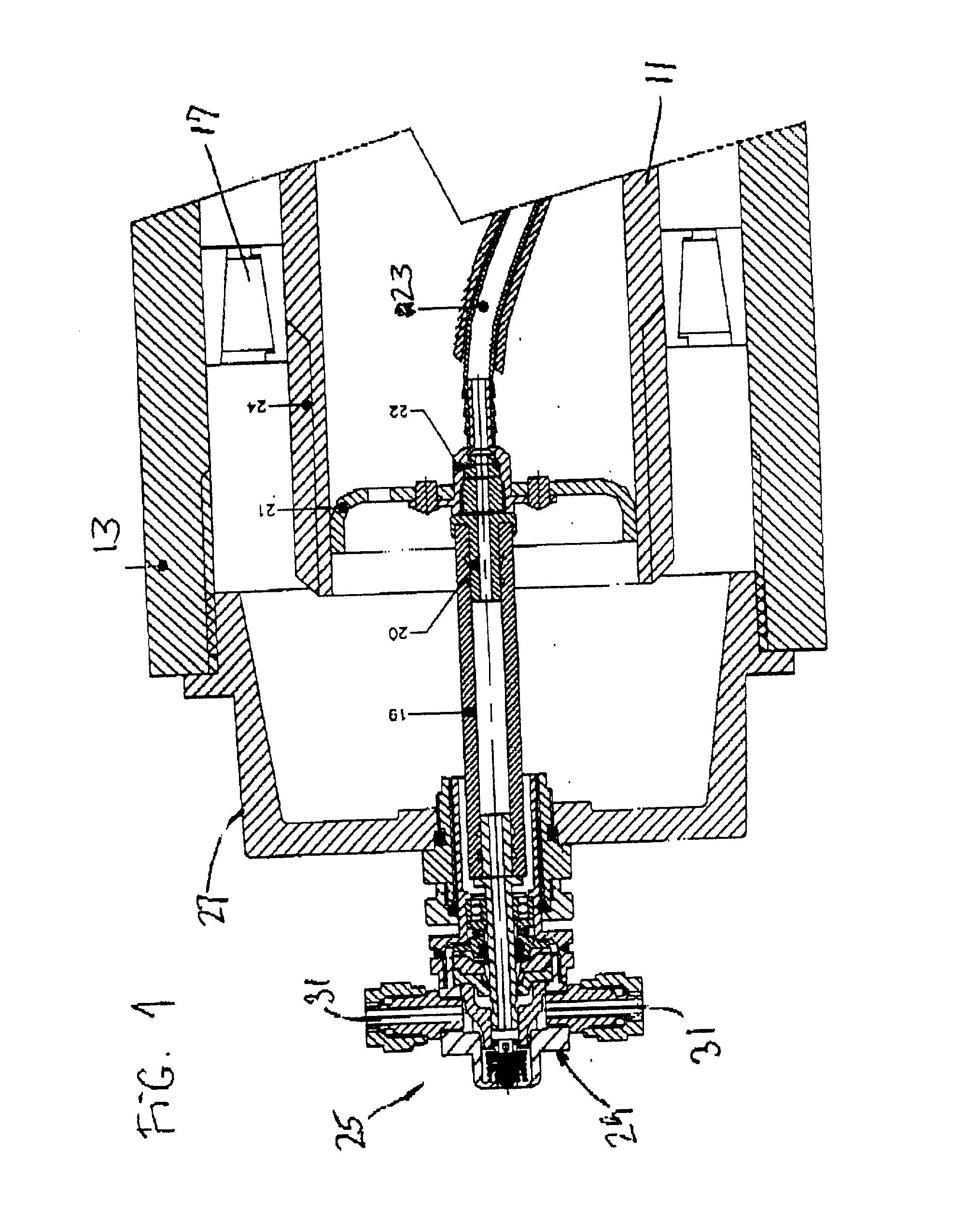
[0016] In FIG. 1, the end of axle 11 of a motor vehicle, such as in a truck, a trailer or a large bus, is shown. A wheel's hub 13 for mounting a single or double tire is mounted on the end of axle 11 by means of bearings 17.

[0017] The pressurized air pipe 21 enters the hollow axle 11 and extends towards the end where the wheel is mounted, where a flexible rubber and cloth pipe section 23 connects it axially to the rotary coupling 25 of the present invention, which is mounted on the wheel's hub cover 27 that protects the bearings 17. In FIG. 1, the body 29 of the coupling 25 can be seen. Two orifices 31 are shown for connecting the coupling 25 by means of the respective hose sections to the nozzles of the pair of tires. The coupling 25 provides continuous sealed communication between the pipe 21 and the tires, thereby bridging the relative movement between the tires due to the wheel's rotation. The pair of orifices 31 are placed radially opposite each other for a better dynamic balan...


PUM


Abstract

A pneumatic rotary coupling (25) for an air pressure installation for one or more wheels of a vehicle. The coupling's tube (49) has one end formed in the shape of a nozzle which extends in the plane of the wheel, disposed as an axial extension of the wheel's axle end. The tube is located rotary and slidable inside block (35) that is fixed to the wheel's hub cover. A cover (37) fixed to the block presents a chamber (45) with an edge that defines a seat for a plastic bushing (47) that supports the coupling's tube. The external surface of this bushing is conformed by grooves (53) that communicate the chamber towards the orifices linking with the tires. The coupling includes a valve (75) that is pushed open by the tube in the event of outward wheel offset, thereby depressurizing the chamber. The tube further includes grooves (87) for bypassing a seal (57) in the event of inward wheel offset, thereby depressurizing the chamber through a vent opening (65). In either case, the chamber depressurization signals the fault to the driver. The vent opening is in a circumferential recess (71) for housing an o-ring (73) that prevents dust, dirt and other undesirable particles from entering the coupling and the wheel bearings.

Description

[0001] The present invention relates to rotary couplings for mounting on wheels of a vehicle, to communicate the pressurized air of the tires with a pneumatic system installed onboard the vehicle, to track and control the pressure of the tires, compensating eventually for slight leaks by supplying air from a compressed air source, typically a compressor system in a bus or lorry or a pressurized air reservoir in a trailer. These couplings provide the pneumatically sealed connection between the installation considered as static and the rotary part, which as well can be affected by other relative movements such as vibrations.[0002] The present invention also concerns early indication of wear in wheel bearings by means of air-leak valves provided in the couplings to prevent catastrophic failure of the wheel mounting at the end of the vehicle's axle.BRIEF DESCRIPTION OF THE PRIOR ART[0003] In large and medium-sized vehicles, either passenger or cargo, it is of particular importance to co...

Claims


Application Information

Patent Timeline
IPC IPC(8): B60C23/00
CPCB60C23/003B60C23/00318B60C23/00345B60C23/00354B60C23/00363
Inventor COLUSSI, RAFAEL A.VENICA, NESTOR J.
Owner COL VEN
Why Eureka
Try Eureka