Friction plunge riveting

a technology of riveting and plunge riveting, which is applied in the direction of soldering apparatus, manufacturing tools,auxillary welding devices, etc., can solve the problems of compromising the service performance of joined components, high cost of mechanical fastening,

Inactive Publication Date: 2002-09-12
ARCONIC INC
View PDF0 Cites 166 Cited by
  • Summary
  • Abstract
  • Description
  • Claims
  • Application Information

AI Technical Summary

Problems solved by technology

Mechanical fastening is also expensive, prone to seepage of environmental elements (salt water, condensation, and the like) and often loosens over time.
Loosening of fastened joints may compromise the service performance of the joined components.
Frictional heat is generated from either side of the stack.

Method used


Image

  • Friction plunge riveting
  • Friction plunge riveting
  • Friction plunge riveting

Examples


Embodiment Construction

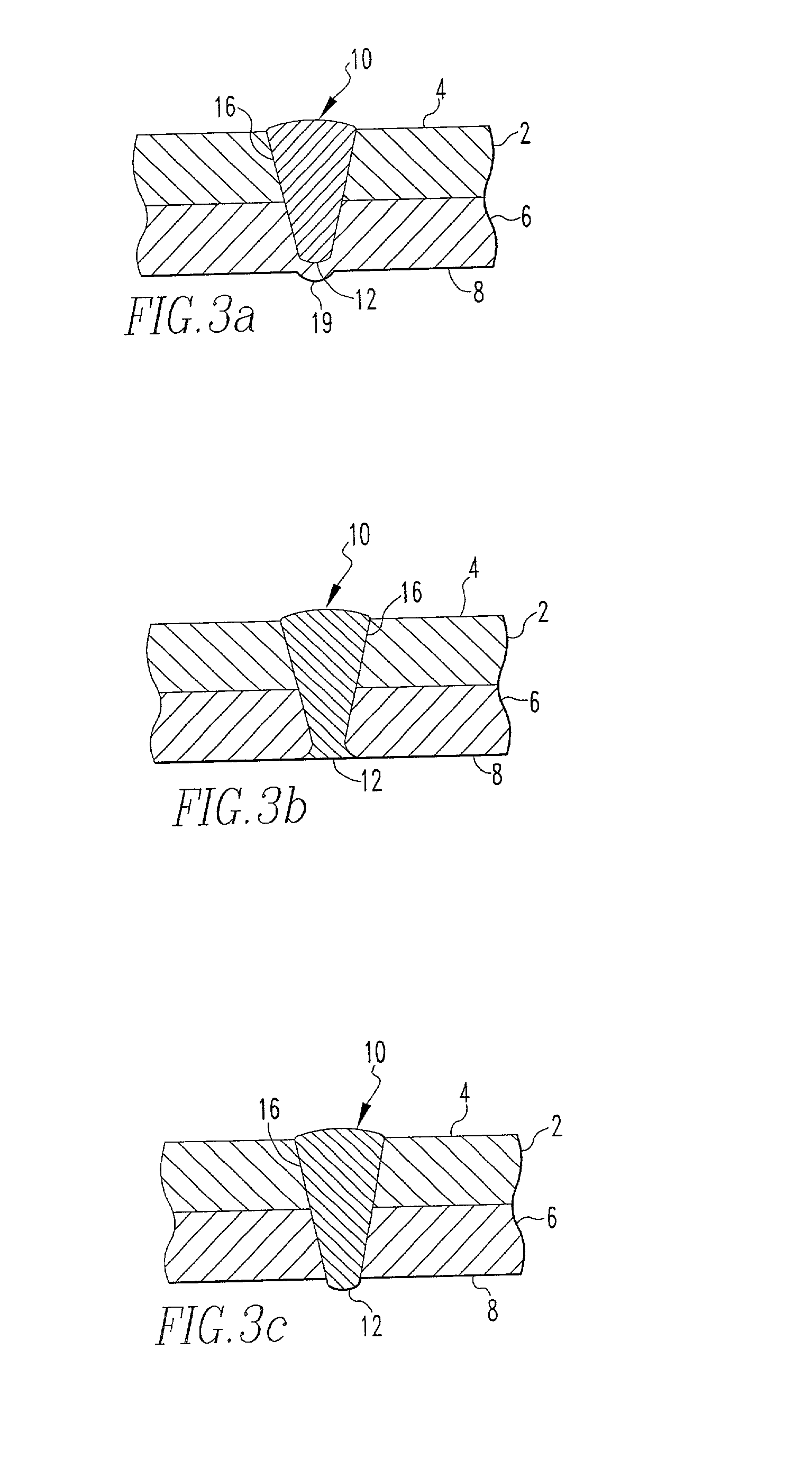
[0050] Two sheets of 2 mm thick aluminum alloy AA 6082-T6 (Vickers Hardness value of 113) were joined together with a cone-shaped rivet made of 2014-T6 aluminum (Vickers Hardness value of 162). The rivet had a 10 mm diameter flat tip and an included angle as shown in FIG. 3a.

[0051] It will be readily appreciated by those skilled in the art that modifications may be made to the invention without departing from the concepts disclosed in the foregoing description. Such modifications are to be considered as included within the following claims unless the claims, by their language, expressly state otherwise. Accordingly, the particular embodiments described in detail herein are illustrative only and are not limiting to the scope of the invention which is to be given the full breadth of the appended claims and any and all equivalents thereof.


PUM

PropertyMeasurementUnit
angleaaaaaaaaaa
angleaaaaaaaaaa
diameteraaaaaaaaaa

Abstract

A method of joining a pair of metal components with a rivet having a hardness that is substantially similar to at least one of the metal components. The metal components are stack upon each other and the rivet is rotated and simultaneously plunged in the metal components under pressure to friction weld and metallurgically bond the rivet to the metal components.

Description

[0001] This application claims the benefit of U.S. application Ser. No. 60 / 257,329, filed Dec. 20, 2000 entitled "A Friction Plunge Riveting Process".[0002] 1. Field of the Invention[0003] The present invention relates to a process for joining or riveting two or more pieces of lapped metal together. The method allows a range of non-ferrous and ferrous metals to be joined, e.g., aluminum, magnesium, copper, titanium, iron, and their respective alloys. More particularly, the invention represents an alternative process for riveting two or more aluminum alloy products together.[0004] 2. Prior Art[0005] Conventional solid-phase welding (friction welding) involves rubbing two surfaces together under pressure in relative motion for sufficient time until metal between the two surfaces becomes thermally softened and in a plastic state. As shown in FIG. 1a, friction welding commonly involves rotating a first component A under pressure against a second component B. Alternatively, the component...

Claims


Application Information

Patent Timeline
Patent Type & Authority Applications(United States)
IPC IPC(8): B21J15/02B21J15/12B23K20/12
CPCB21J15/027B23K20/12B23K20/127B23K20/129B23K20/1295
Inventor STOL, ISRAELTHOMAS, WAYNE M.THREADGILL, PHILIP L.
Owner ARCONIC INC
Why Eureka
Try Eureka