Cellular base station antenna

a technology of antenna assembly and cell base station, which is applied in the direction of individual energised antenna array, antenna equipment with additional functions, transmission, etc., can solve the problems of affecting the mechanical antenna mount, affecting the performance of the antenna, and affecting the operation of the antenna

Inactive Publication Date: 2002-09-12
COMMSCOPE TECH LLC
View PDF0 Cites 28 Cited by
  • Summary
  • Abstract
  • Description
  • Claims
  • Application Information

AI Technical Summary

Problems solved by technology

The need may arise due to a number of factors, including new construction, which may create obstacles, vegetation growth, or other changes in the surrounding environment.
Once the assembly has been installed on a tower, however, this becomes difficult.
It is also possible to change the azimuth and elevation of the individual antennas, but such a method is expensive when applied to several antennas.
Also, the mechanical device required to adjust the azimuth and elevation may interfere with the mechanical antenna mount.
The phase adjusters currently in use, however, have numerous drawbacks.
First, the conductor is often made of brass which is expensive to etch and cut.
The conductor does not cover the entire width at the capacitor, which decreases the effectiveness of the capacitance.
Another problem with current phase adjusters is the coupling of a power divider to the phase adjuster.
Using a variety of cables makes manufacturing difficult since the cables have to be soldered together.
Also, sin

Method used


Image

  • Cellular base station antenna
  • Cellular base station antenna
  • Cellular base station antenna

Examples


Embodiment Construction

[0022] An antenna assembly for emitting a signal includes at least two antennas divided into two groups. A first phase adjuster is coupled to the first antenna group, and are adapted to adjust a phase angle of the first group. A second phase adjuster is coupled to the second antenna group. The second phase adjuster is adapted to adjust a phase angle of the second group. Also coupled to the second phase adjuster is the first phase adjuster, such that an adjustment of the first phase adjuster causes an adjustment of the second phase adjuster.

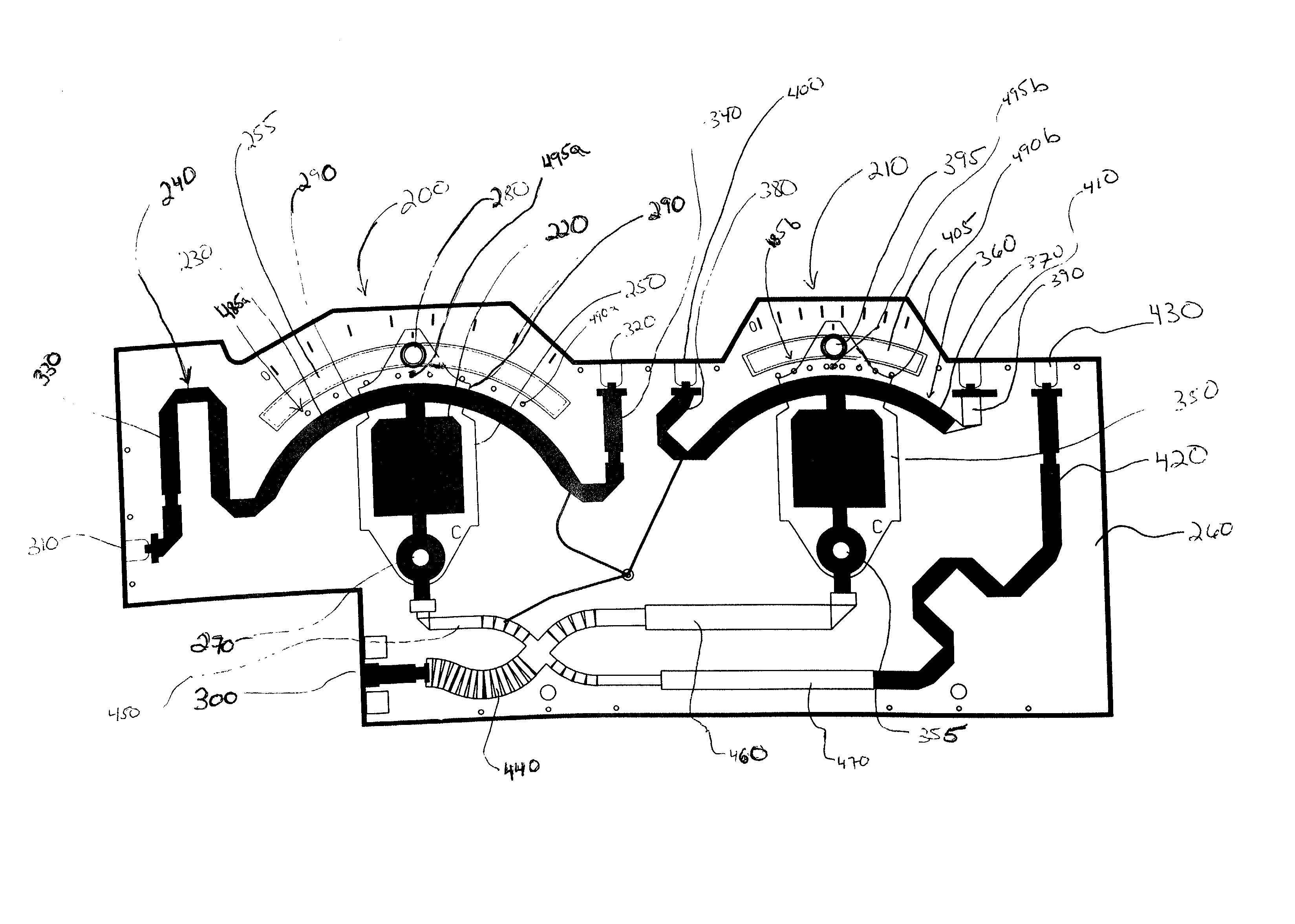
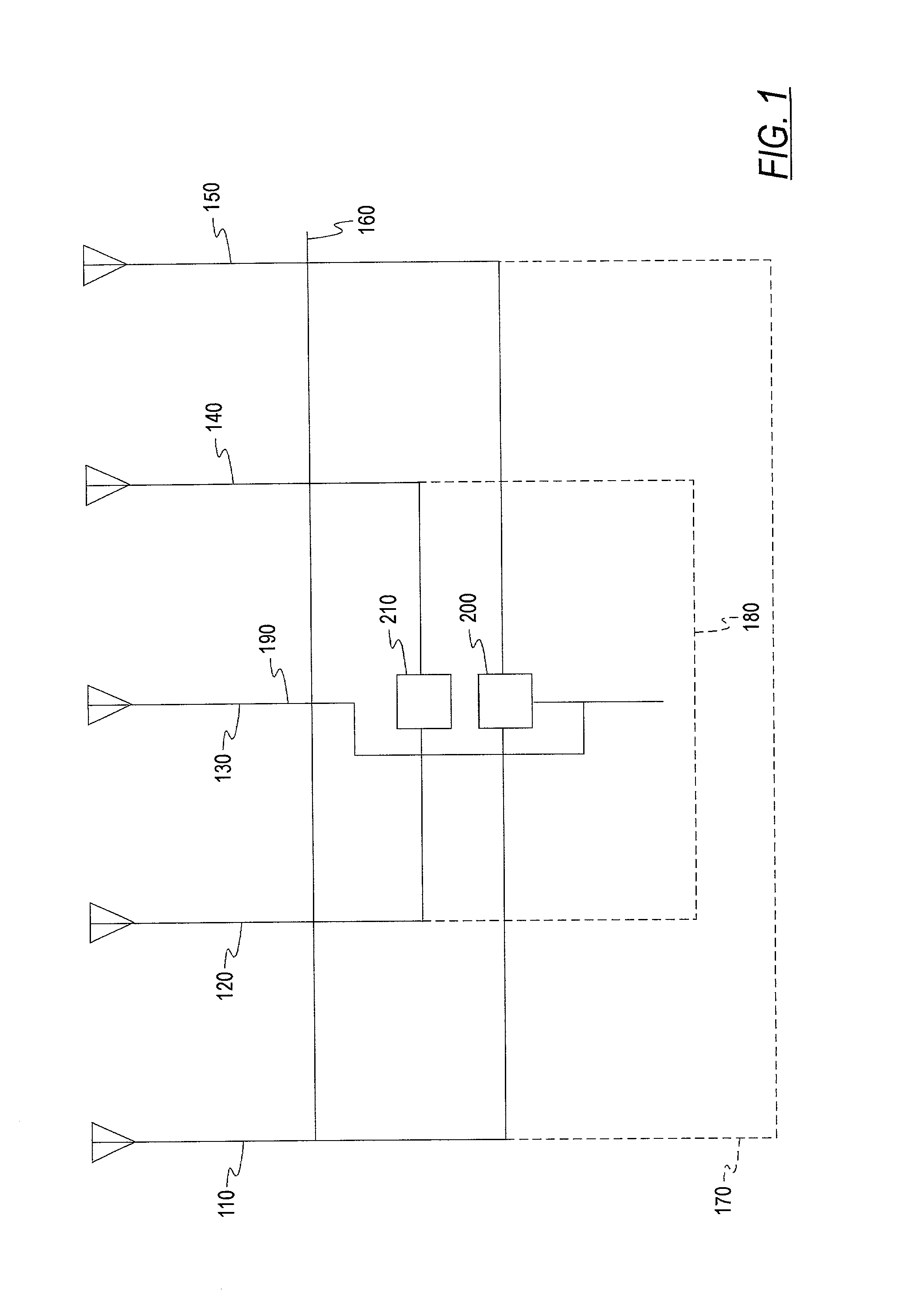
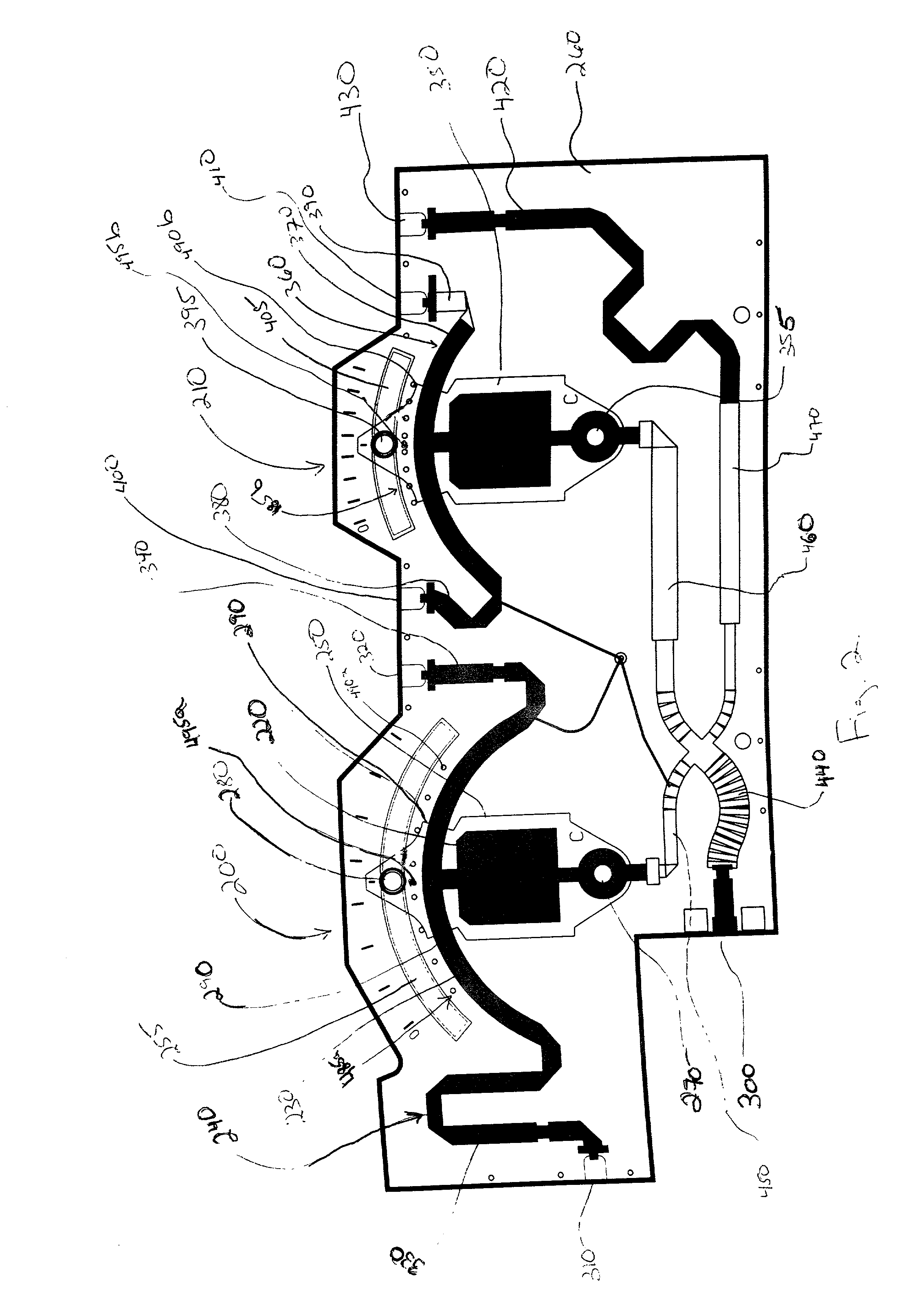
[0023] FIG. 1 is a side view of an antenna assembly 100 of the present invention. The antenna assembly 100 is comprised of a plurality of antennas 110, 120, 130, 140, 150 disposed along a panel 160. The antennas 110, 120, 130, 140, 150 are grouped into a first group 170, a second group 180, and a third group 190. The first antenna 110 and the fifth antenna 150 are in the first group 170. The second antenna 120 and the fourth antenna 140 are in the...


PUM


Abstract

An antenna assembly for emitting a signal. The antenna assembly includes at least two antennas which are separated into a first group and a second group. Both groups of antennas are mounted on a panel. A first phase adjuster is coupled to the first antenna group. The first phase adjuster is also coupled to a second phase adjuster, which is also coupled to said second antenna group. The first phase adjuster is coupled to the second phase adjuster, such that an adjustment of the first phase adjuster causes an adjustment of the second phase adjuster. The first phase adjuster is adapted to adjust a phase angle of the signal of the first antenna group, while the second phase adjuster is adapted to adjust a phase angle of the signal of said second antenna group.

Description

FIELD OF THE INVENTION[0001] The present invention relates generally to an antenna assembly having variable radiation patterns and, more particularly, to a phase shifting assembly for an antenna assembly having a variable radiation downtilt angle which is electrically adjustable.BACKGROUND OF THE INVENTION[0002] In many passive antenna assemblies, it is often desired to be able to adjust a radiation pattern of the antenna assembly after the antenna assembly has been installed on a tower. The need may arise due to a number of factors, including new construction, which may create obstacles, vegetation growth, or other changes in the surrounding environment. It may also be desired to alter the radiation pattern due to performance studies or to alter the shape of the area the antenna covers.[0003] There are various ways that the radiation pattern may be altered. One method is to physically change the location of the antenna assembly. Once the assembly has been installed on a tower, howe...

Claims


Application Information

Patent Timeline
IPC IPC(8): H01Q1/24H01Q1/44H01Q3/32H01Q3/34H01Q21/08
CPCH01Q1/246H01Q3/32H01Q21/08H04B7/155
Inventor ZIMMERMAN, MARTIN L.PASKE, JAMIEGIACOBAZZI, JIMLINEHAN, KEVIN E.
Owner COMMSCOPE TECH LLC
Why Eureka
Try Eureka