Vanity mirror

a vanity mirror and mirror technology, applied in the field of vanity mirrors, can solve the problems of increasing manufacturing costs, and achieve the effect of low manufacturing costs

Inactive Publication Date: 2002-09-12
T & T
View PDF0 Cites 8 Cited by
  • Summary
  • Abstract
  • Description
  • Claims
  • Application Information

AI Technical Summary

Benefits of technology

0009] The present invention has been made to solve the afore discussed problems and its object is to provide a vanity mirror which is as thin as possible and capable of having the manufacturing cost as low as possible by having a fewer number of parts. Therefore, the vanity mirror of the invention essentially comprises a body base having a mirror attached thereto; a cover plate openably attached to said body base through a hinge mechanism; a switch turned on and off though opening and closing of said cover plate; and an illumination unit composed of a lamp connected to lead wires and a lens plate adapted to be attached and detached to said base plate; said illumination unit detachably attached to body base body base.

Problems solved by technology

There is another problem that the need for connection of each fuse bulb 26 to a bus bar 27 by way of the bulb holding metal member 25 causes the manufacturing cost to increase.

Method used


Image

  • Vanity mirror
  • Vanity mirror
  • Vanity mirror

Examples


Embodiment Construction

[0018] Hereinafter, the vanity mirror according to the present invention will be explained in the form of one embodiment.

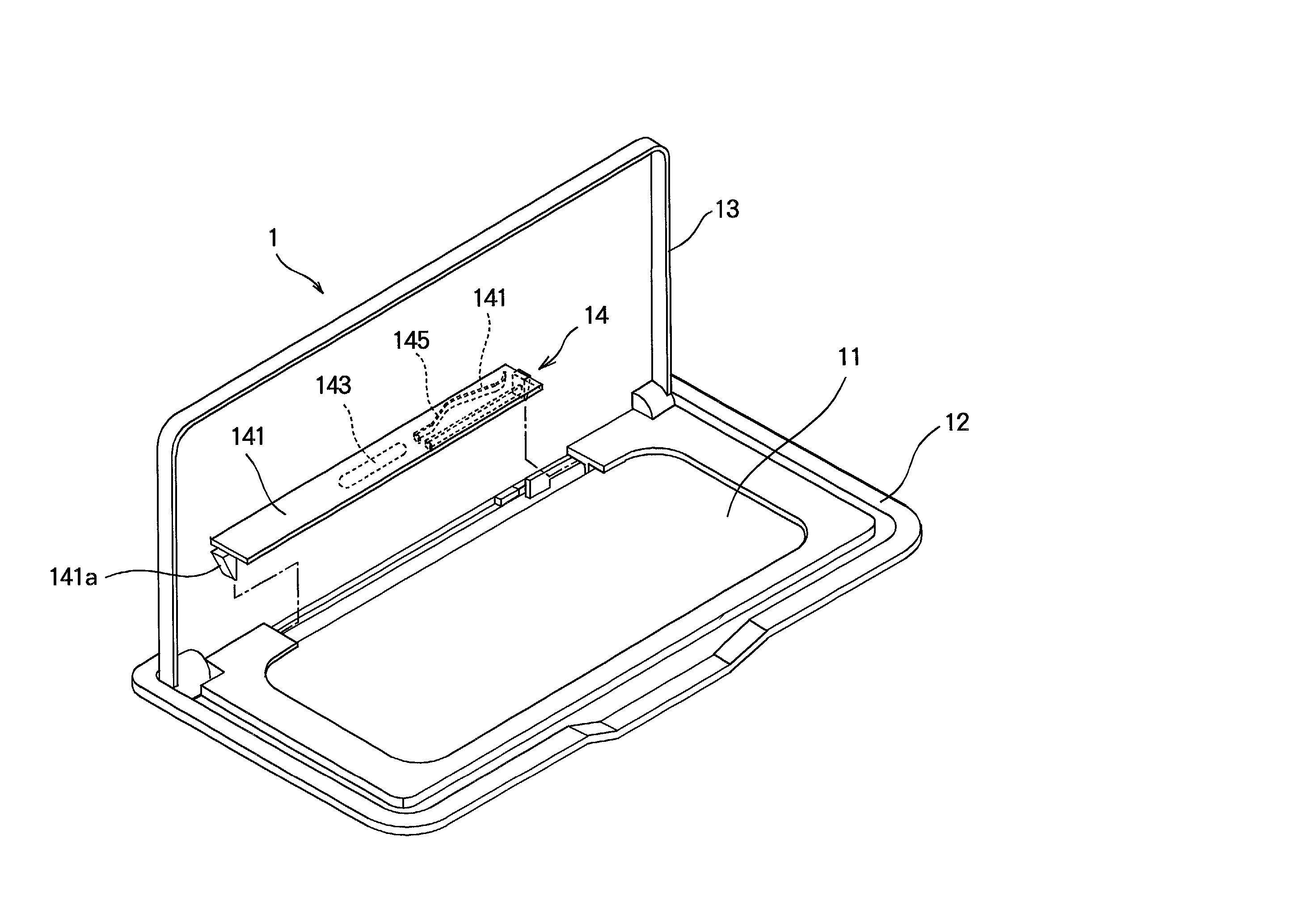
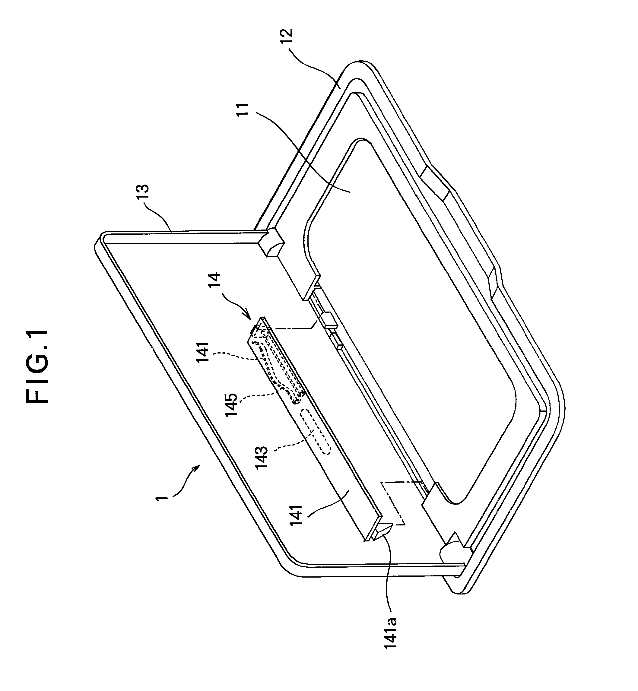
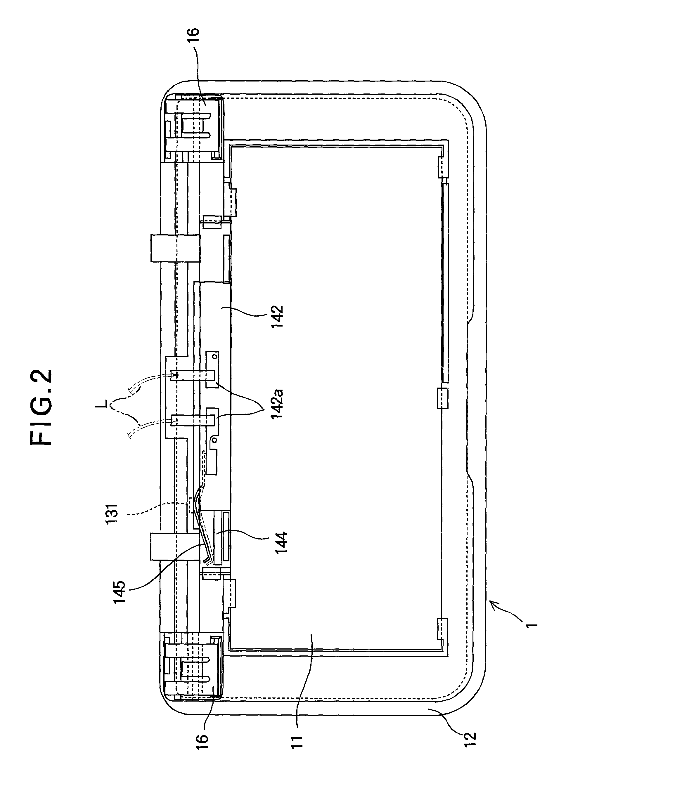
[0019] First of all, the entire structure of the vanity mirror according to the invention will be discussed referring to FIG. 1 through FIG. 4. Here, FIG. 1 is a perspective view of the vanity mirror according to the invention; FIG. 2 is a bottom view thereof; FIG. 3 is an exploded perspective view thereof; and FIG. 4 is a perspective view of a disassembled illumination unit.

[0020] In those figures, the numeral 1 denotes a vanity mirror of the invention. Said vanity mirror 1 is a similar type to the one in the prior art which is to be attached to a sun visor in the automobile and is composed of a mirror body 11 centrally provided in a body base 12, a cover 13 openably attached to said body base 12 by way of a hinge mechanism and illumination unit 14 attached to the top of said mirror body 11 and adapted to be powered on and off through opening and closing of said ...


PUM


Abstract

A vanity mirror comprising a body base having a mirror attached thereto; a cover plate openably attached to said body base through a hinge mechanism; a switch turned on and off though opening and closing of said cover plate; and an illumination unit composed of a lamp connected to lead wires and a lens plate adapted to be attached and detached to said base plate; said illumination unit detachably attached to body base body base.

Description

BACKGROUND OF THE INVENTION[0001] The present invention relates to an improved vanity mirror and more particularly to a vanity mirror which is capable of involving a fewer number of parts involved as well as reducing the thickness of the vanity mirror.[0002] Some vanity mirrors used in the automobile, particularly those attached to the sun visor therein, use a lamp for illumination purposes during the night operations for the passenger's sake.[0003] FIG. 7 and FIG. 8 shows a conventional vanity mirror, in which the numeral 20 denotes a vanity mirror composed of a body base 22 centrally attached with a mirror 21, a cover 23 openably attached to said body base 22 by way of a hinge mechanism and lamp sections 24 attached to the opposite sides of said mirror 21 and adapted to be powered on and off through opening of said cover 23.[0004] Further, said lamp sections 24 are composed of recesses 221 formed on both sides of said mirror 21 in the body base 22, lamp holding metal members 25 at...

Claims


Application Information

Patent Timeline
Patent Type & Authority Applications(United States)
IPC IPC(8): B60N3/00B60J3/02B60Q3/02
CPCB60J3/0282B60Q3/252
Inventor OKANO, HIROFUMIMOCHIDA, TETSUO
Owner T & T
Why Eureka
Try Eureka