
Control system for controlling safety-critical processes

a control system and process technology, applied in the direction of transmission system, programme control, transmission system, etc., can solve the problems of inability to send data by any station to any other station, high cost, and relatively complex

Inactive Publication Date: 2002-09-12
PILZ (COMPANY)
View PDF0 Cites 46 Cited by
  • Summary
  • Abstract
  • Description
  • Claims
  • Application Information

AI Technical Summary

Benefits of technology

[0010] It is an object of the present invention to provide a control system that provides failsafe communication between units involved in controlling a safety-critical process.

Problems solved by technology

This has the result that no data can be sent by any station to any other station without "permission" and control of the bus master.
Usually, the bus master is a standard module which implements the protocols specified for the field bus, and which is often relatively complex and, thus, considerably expensive.
Although the use of field buses offers numerous advantages, mainly with respect to the high cabling effort that would otherwise be required, it was not possible heretofore to employ field buses in practical use for controlling safety-critical processes.
The reason is that due to their structure being freely accessible for any units, the degree of failsafety necessary for controlling safety-critical processes could not be guaranteed.
However, implementing such arrangements is very laborious and costly in the development and construction of a failsafe control system, since one cannot make use of standard modules for this purpose any longer, but is required to develop the complex bus master as such.
In addition, such an approach is of disadvantage also in operation of a control system based thereon, because in the control of complex processes the safety-directed communication amounts to only 10% of the whole communication volume.
The known approach leads therefore to the disadvantage that the bus master is made "safe" at high expense, although this is not necessary for 90% and more of the communication volume controlled by it.

Method used


Image

  • Control system for controlling safety-critical processes
  • Control system for controlling safety-critical processes
  • Control system for controlling safety-critical processes

Examples


Embodiment Construction

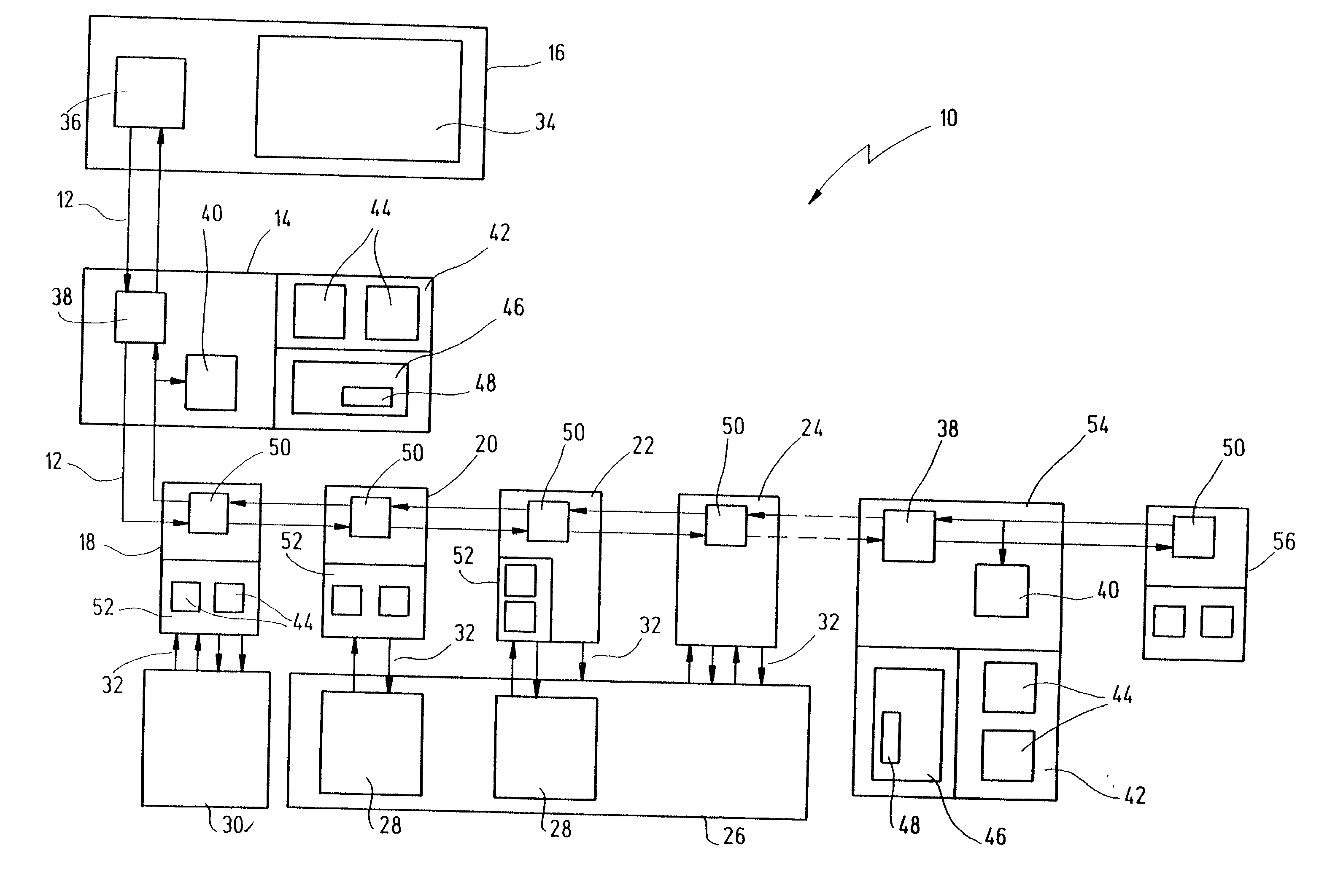
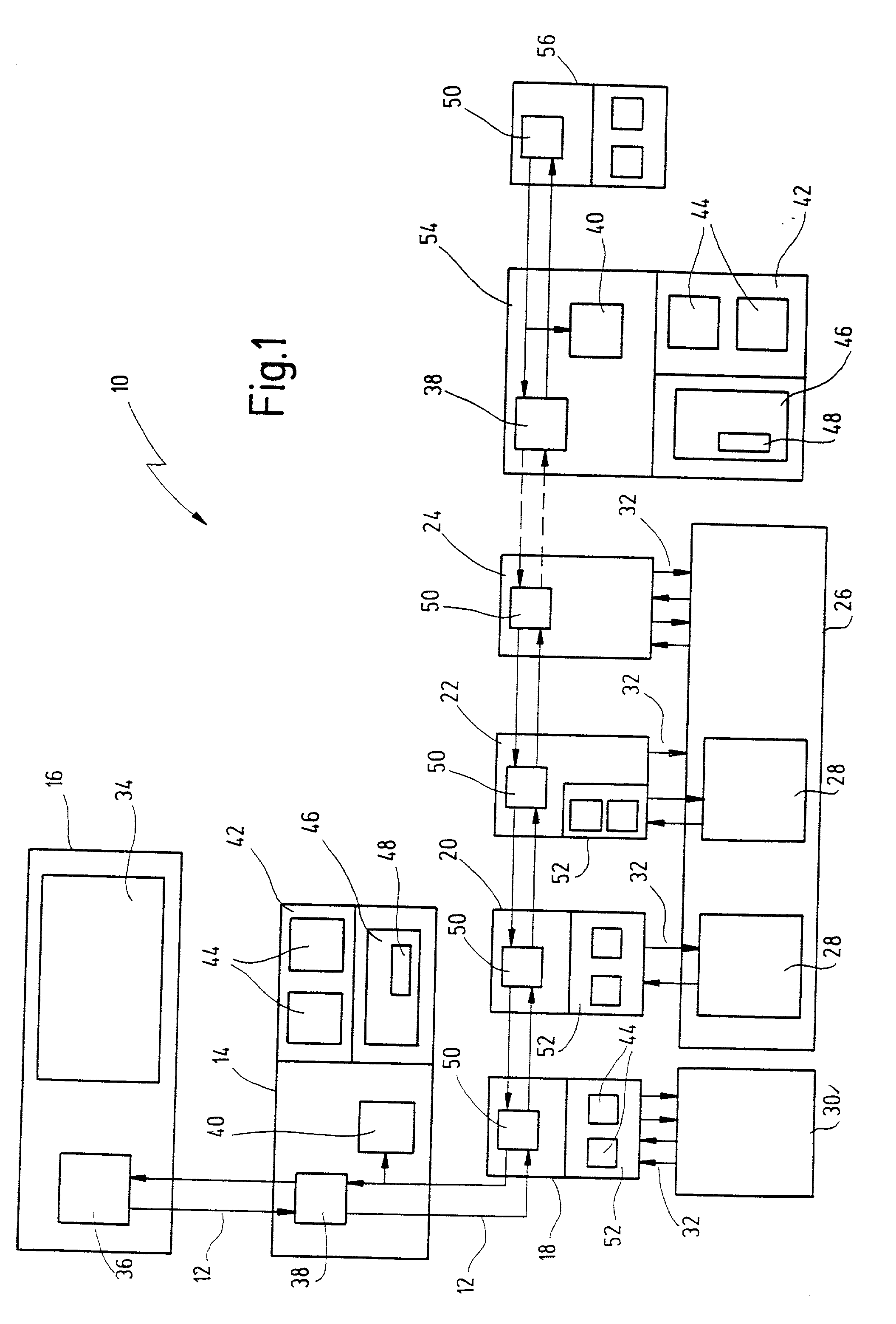
[0049] In FIG. 1, a control system according to the invention is indicated in its entirety by reference numeral 10.

[0050] The control system 10 is based on a field bus 12, in the present case an Interbus. Connected to the field bus 12 are a first control unit 14, a second control unit 16 and a total of four signal units 18, 20, 22 and 24 shown by way of example. The first control unit 14 is a safe control unit, while the second control unit 16 is a standard control unit.

[0051] An automated overall process, containing two safety-critical partial processes 28, shown by way of example, is indicated by reference numeral 26. The parts of the overall process outside the safety-critical partial processes 28 are not safety-critical, i.e. they do not require any safety-directed additional measures. The overall process 26 relates, by way of example, to the automated control of a press, where the feeding processes for the parts to be processed (not shown) represent non-safety-critical partial ...


PUM


Abstract

The present invention describes a control system for controlling safety-critical processes. The control system has a first control unit for controlling a safety-critical process and at least one signal unit linked to the safety-critical process via I / O channels. It further comprises a field bus connecting said first control unit and said signal unit, and a bus master for controlling communication on said field bus. Said first control unit and said signal unit each comprise safety-directed arrangements for ensuring failsafe communication among each other. Said bus master is connected to said field bus separately from said first control unit and said signal unit.

Description

CROSSREFERENCES TO RELATED APPLICATIONS[0001] This application is a continuation of copending international patent application PCT / EP00 / 05763 filed on Jun. 21, 2000 and designating the U.S., which claims priority of German patent application DE 199 28 517.9 filed on Jun. 22, 1999.BACKGROUND OF THE INVENTION[0002] The present invention relates to a control system for controlling safety-critical processes, having a first control unit for controlling safety-critical processes and at least one signal unit linked to the safety-critical processes via I / O channels, and further having a field bus connecting the first control unit and the signal unit, and a bus master for controlling communication on the field bus, said first control unit and said signal unit comprising safety-directed arrangements for ensuring failsafe communication among each other.[0003] Use of field buses for data communication between separate units involved in the control of a process is sufficiently known today in con...

Claims


Application Information

Patent Timeline
IPC IPC(8): G05B9/03G05B9/02G05B19/042G05B19/05G05B19/418H04L12/403
CPCG05B19/0428G05B19/4185G05B2219/24024G05B2219/25139G05B2219/25324G05B2219/31245H04L12/403H04L2012/4026Y02P90/18Y02P90/02
Inventor HECKEL, ANDREASWOHNHAAS, KLAUSRUPP, ROLAND
Owner PILZ (COMPANY)
Learn More