
Packet transmission scheduling in a data communication network

a data communication network and packet transmission technology, applied in data switching networks, digital transmission, time-division multiplexing selection, etc., can solve the problems of legacy equipment not supporting all of the packet scheduling features of other more fully featured network equipment, and certain communications may be intolerant to delays, etc., to achieve efficient data packet scheduling

Inactive Publication Date: 2002-09-12
MAPLE OPTICAL SYST
View PDF16 Cites 30 Cited by
  • Summary
  • Abstract
  • Description
  • Claims
  • Application Information

AI Technical Summary

Benefits of technology

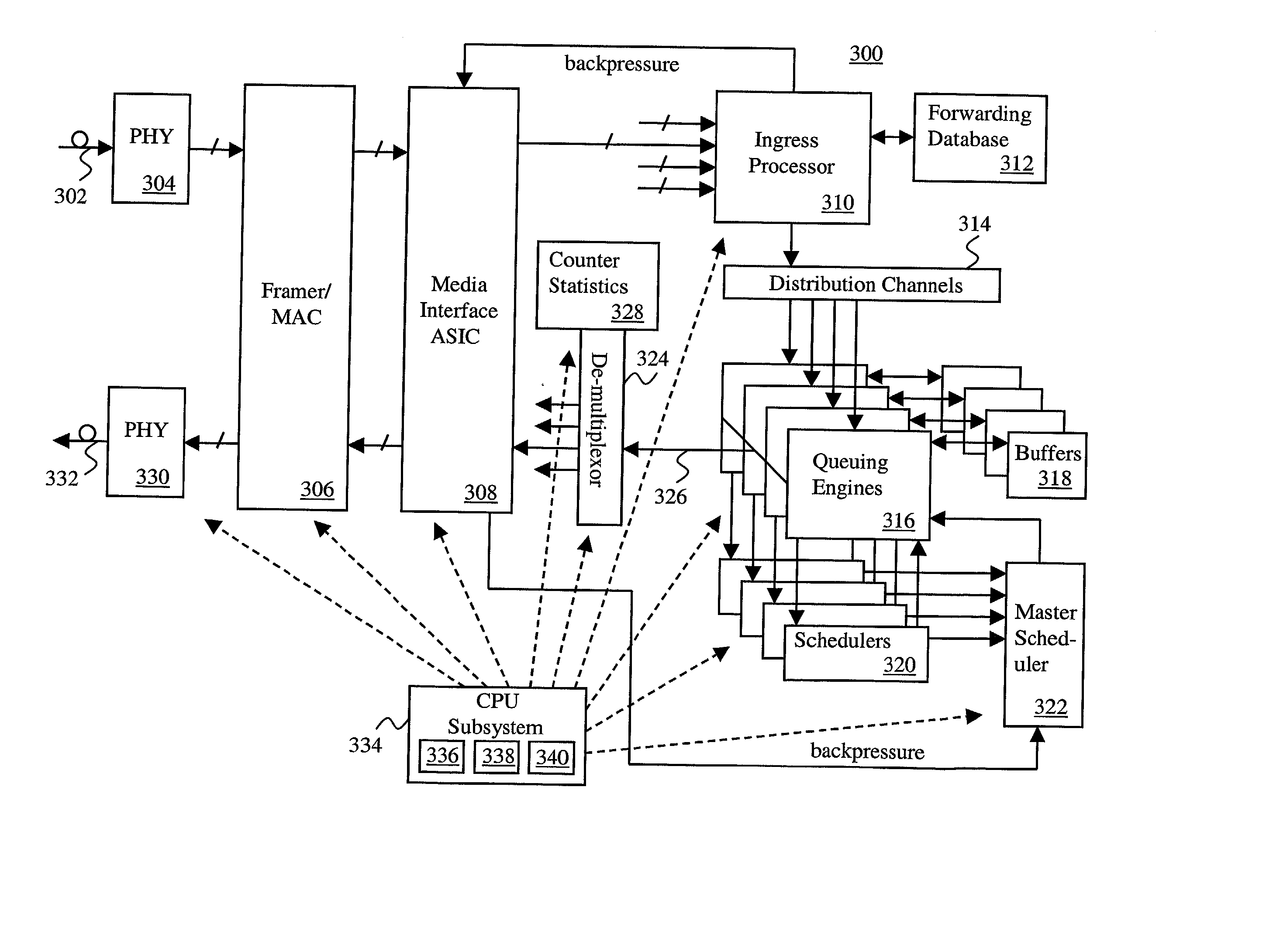
[0009] The present invention is directed toward methods and apparatus for packet transmission scheduling in a data communication network. In one aspect, received data packets are assigned to an appropriate one of a plurality of scheduling heap data structures. Each scheduling heap data structure is percolated to identify a most eligible data packet in each heap data structure. A highest-priority one of the most-eligible data packets is identifying by prioritizing among the most-eligible data packets. This packet may then be transmitted. To accomplish scheduling, a plurality of schedulers may be arranged in a hierarchy, including a number of schedulers at a first level and a master scheduler at a higher level. This is useful because the scheduling tasks may be distributed among the hierarchy of schedulers to efficiently handle data packet scheduling.

Problems solved by technology

For example, certain communications may be intolerant to delays, such as voice or video communications.
Legacy equipment may not support all of the packet scheduling features of other more fully featured network equipment.
However, it may be desired to use legacy equipment in conjunction with fully featured equipment for reasons such as cost.

Method used


Image

  • Packet transmission scheduling in a data communication network
  • Packet transmission scheduling in a data communication network
  • Packet transmission scheduling in a data communication network

Examples


Embodiment Construction

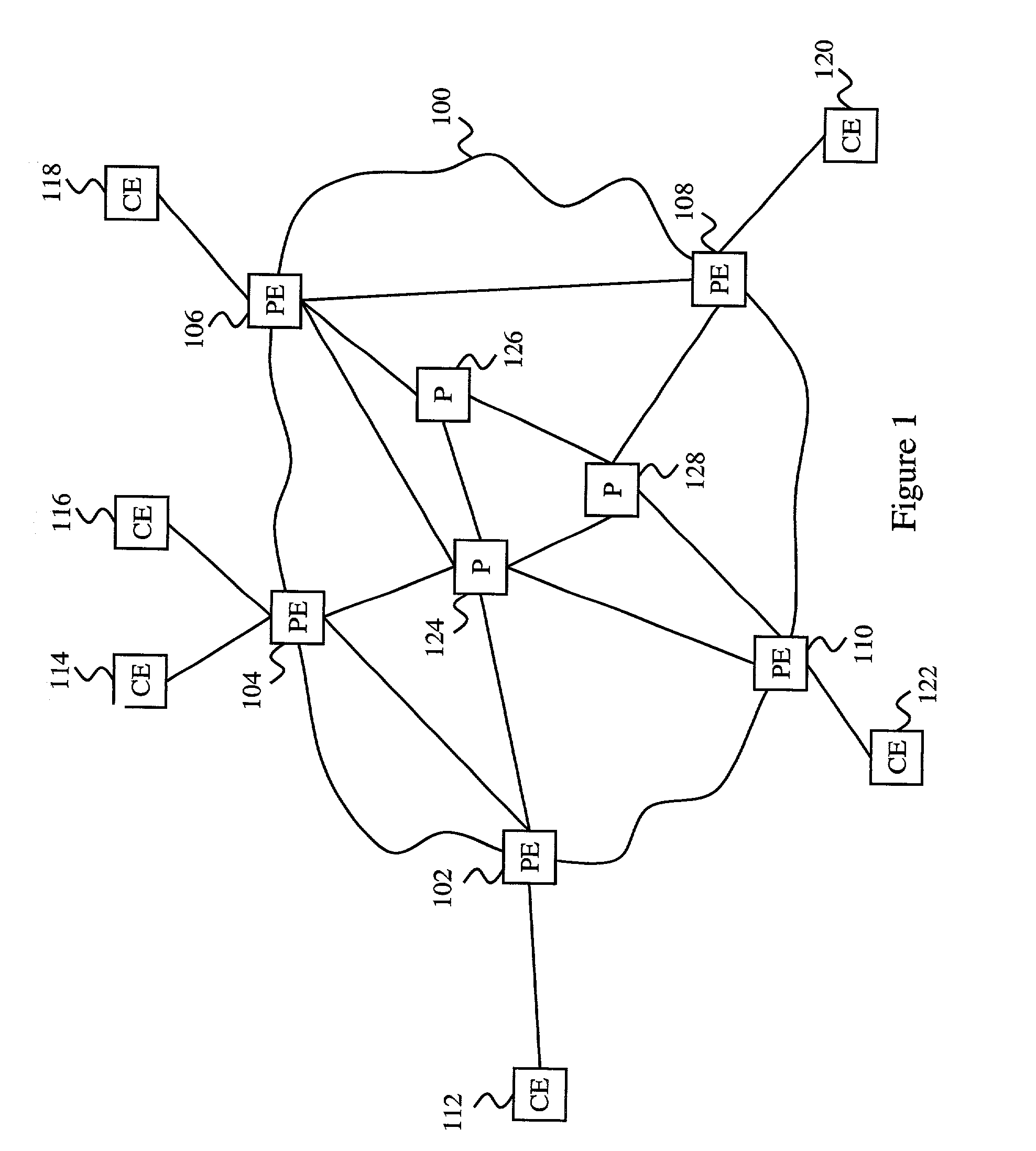
[0030] FIG. 1 illustrates a block schematic diagram of a network domain (also referred to as a network "cloud") 100 in which the present invention may be implemented. The network 100 includes edge equipment (also referred to as provider equipment or, simply, "PE") 102, 104, 106, 108, 110 located at the periphery of the domain 100. Edge equipment 102-110 may each communicate with corresponding ones of external equipment (also referred to as customer equipment or, simply, "CE") 112, 114, 116, 118, 120 and 122 and may also communicate with each other via network links. As shown in FIG. 1, for example, edge equipment 102 is coupled to external equipment 112 and to edge equipment 104. Edge equipment 104 is also coupled to external equipment 114 and 116. In addition, edge equipment 106 is coupled to external equipment 118 and to edge equipment 108, while edge equipment 108 is also coupled to external equipment 120. And, edge equipment 110 is coupled to external equipment 122.

[0031] The ex...


PUM


Abstract

The present invention is directed toward methods and apparatus for packet transmission scheduling in a data communication network. In one aspect, received data packets are assigned to an appropriate one of a plurality of scheduling heap data structures. Each scheduling heap data structure is percolated to identify a most eligible data packet in each heap data structure. A highest-priority one of the most-eligible data packets is identifying by prioritizing among the most-eligible data packets. This is useful because the scheduling tasks may be distributed among the hierarchy of schedulers to efficiently handle data packet scheduling. Another aspect provides a technique for combining priority schemes, such as strict priority and weighted fair queuing. This is useful because packets may have equal priorities or no priorities, such as in the case of certain legacy equipment.

Description

[0001] This application claims the benefit of U.S. Provisional Application Serial No. 60 / 271,805, filed Feb. 26, 2001.[0002] The contents of U.S. patent application Ser. No. ______, filed on the same day as this application, and entitled, "DATA PACKET TRANSMISSION SCHEDULING"; U.S. patent application Ser. No. ______, filed on the same day as this application, and entitled, "DATA PACKET TRANSMISSION SCHEDULING USING A PARTITIONED HEAP"; and U.S. patent application Ser. No. ______ filed on the same day as this application, and entitled, "DATA PACKET TRANSMISSION SCHEDULING BASED ON ANTICIPATED FINISH TIMES" are hereby incorporated by reference.FIELD OF THE INVENTION[0003] The invention relates to the field of data communication networks. More particularly, the present invention relates to methods and apparatus for scheduling data packets being sent within a data communication network.BACKGROUND OF THE INVENTION[0004] In a network that serves multiple user entities for various differen...

Claims


Application Information

Patent Timeline
IPC IPC(8): H04L12/46H04L12/56H04L29/08H04Q11/04
CPCH04L47/10H04L47/24H04L47/2433H04L47/26H04L47/28H04L47/56H04L47/60H04L47/6215H04L2012/5635H04L2012/5651H04L2012/5679H04L2012/5681H04Q11/0478H04L67/06H04L67/322H04L67/325H04L69/329H04L47/50H04L67/61H04L67/62
Inventor NARAYANA, PIDUGUDHARMAPURIKAR, MAKARANDCHATTOPADHYA, SANDIP
Owner MAPLE OPTICAL SYST
Learn More