
Color image forming apparatus

a technology of color image and forming apparatus, which is applied in the direction of electrographic process apparatus, instruments, optics, etc., can solve the problems of adversely affecting the later image formation, manufacturing errors and varying tolerances, and the difficulty of reducing the size of the image forming apparatus, so as to achieve the effect of not promoting creep in the transfer bel

Inactive Publication Date: 2002-09-12
SEIKO EPSON CORP
View PDF0 Cites 10 Cited by
  • Summary
  • Abstract
  • Description
  • Claims
  • Application Information

AI Technical Summary

Benefits of technology

[0015] It is therefore an object of the invention to provide a color image forming apparatus that can solve the problems as described above, can be miniaturized, and does not promote creep in a transfer belt.
[0016] It is another object of the invention to provide a color image formation apparatus which stabilizes the transfer condition from an image supporting member to a transferring member with a simple driving system.

Problems solved by technology

Thus, the stretching structure of the transfer belt becomes complicated so that it is difficult to reduce the size of the image forming apparatus.
Since a relatively large tension is given to the transfer belt 1 when the image forming apparatus is not activated (the transfer belt is not circulated) for a long time period, creep deformation would occur in the transfer belt, adversely affecting the later image formation.
More practically, however, manufacturing errors and varying tolerances are usually introduced into the image supporting member, the transferring member, or the parts making up their driver units at the manufacturing stage.
Thus, it is practically impossible to completely match the circumferential velocity of the image supporting member and that of the transferring member.
If the difference between the circumferential velocity of the image supporting member and that of the transferring member varies, for example, if the circumferential velocity of the image supporting member is higher than that of the transferring member at one point in time and the former becomes lower than the latter at another point in time, the transfer condition becomes remarkably unstable and a fine image cannot be obtained.
Accordingly, the driving mechanism becomes very complicated and the apparatus size is also increased.
Therefore, the transfer condition would become remarkably unstable as described above, so that a fine image cannot be provided.

Method used


Image

  • Color image forming apparatus
  • Color image forming apparatus
  • Color image forming apparatus

Examples


Embodiment Construction

[0065] Preferred embodiments of the present invention will be described below in detail with reference to the accompanying drawings.

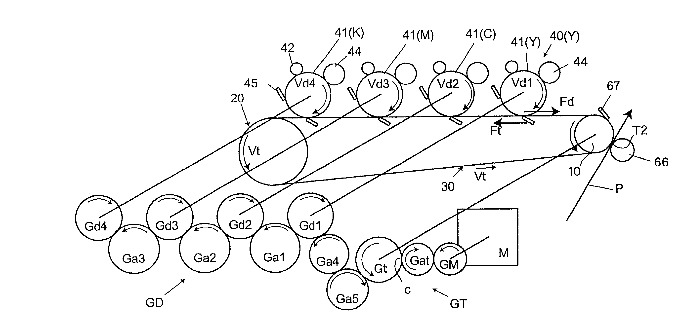
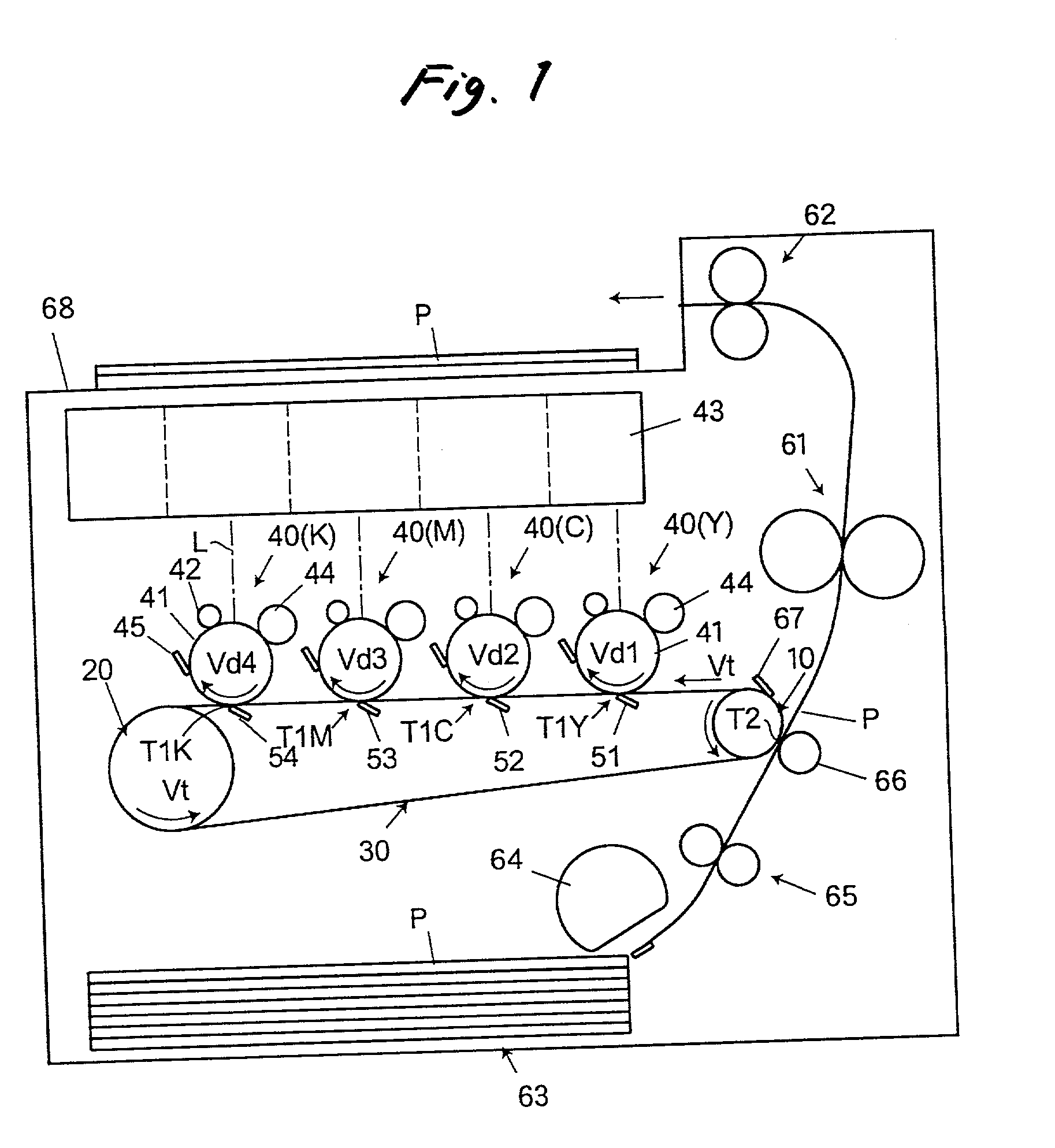
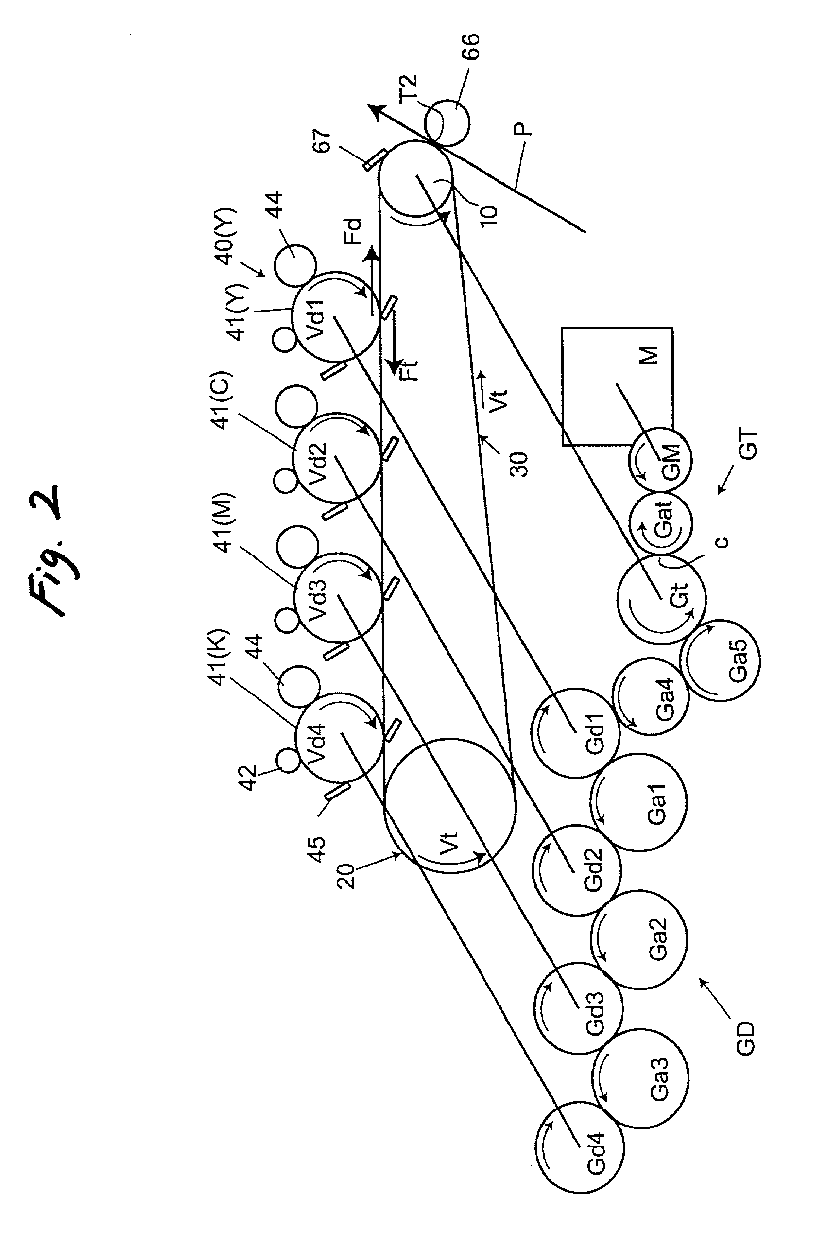
[0066] In a color image forming apparatus shown in FIG. 1, an intermediate transfer belt 30 is looped on a drive roller 10 and a driven roller 20 and circulated in the arrow direction (counterclockwise). A plurality of (four) single-color toner image formers 40 (Y, C, M, and K) are brought into contact with the intermediate transfer belt 30 for sequentially transferring toner images thereon with the aid of individual transferring members 51, 52, 53, and 54 which define respective primary transferring positions T1Y, T1C, T1M, and T1K.

[0067] Each of the single-color toner image formers 40(Y) for yellow, 40(M) for magenta, 40(C) for cyan, and 40(K) for black has a photoconductor 41 having a photosensitive layer on the outer peripheral surface thereof, as an image supporting member, a charging roller 42 for uniformly charging the outer peripheral surface of...


PUM


Abstract

In a color image forming apparatus, a looped belt member is stretched and circulated by at least a drive roller and a driven roller so as to have a tensed side and a slack side. Each of plural image supporting members supports a single color toner image thereon, and abuts onto the slack side of the belt member to define a transferring position at which the toner image is transferred onto either the belt member or a recording medium held by the belt member, while being rotated. A circumferential velocity of each image supporting member is determined so as to be higher than a circulation velocity of the belt member.

Description

BACKGROUND OF THE INVENTION[0001] The present invention relates to a color image forming apparatus using the electrophotographic technology such as a printer, a copy machine, a facsimile machine, or the like. More particularly, the invention relates to a color image forming apparatus in which a plurality of toner images respectively formed by a plurality of single-color toner image formers are sequentially transferred on a transferring member or a recording medium held by the transferring member.[0002] In general, an image forming apparatus and in particular, a tandem image forming apparatus using electrophotography has a photoconductor as an image supporting member having a photosensitive layer on the outer peripheral surface thereof, a charger for uniformly charging the outer peripheral surface of the photoconductor, an exposer for selectively exposing the charged outer peripheral surface to light for forming an electrostatic latent image thereon, and a developer for giving toner ...

Claims


Application Information

Patent Timeline
IPC IPC(8): G03G15/01
CPCG03G2215/0119G03G15/0194
Inventor YODA, KANEOABE, NOBUMASANOMURA, YUJIRO
Owner SEIKO EPSON CORP
Learn More