Compressor

Inactive Publication Date: 2002-09-12
TOYOTA IND CORP
View PDF0 Cites 8 Cited by
  • Summary
  • Abstract
  • Description
  • Claims
  • Application Information

AI Technical Summary

Benefits of technology

0007] In order to overcome such a problem, an object of the present invention is to provide a compress

Problems solved by technology

However, in the case where carbon dioxide is used as refrigerant or the like, the refrigerant is used under the rather high-pressure condit

Method used


Image

  • Compressor
  • Compressor
  • Compressor

Examples


Example

[0013] Embodiments of the present invention will now be described with reference to the accompanying drawings.

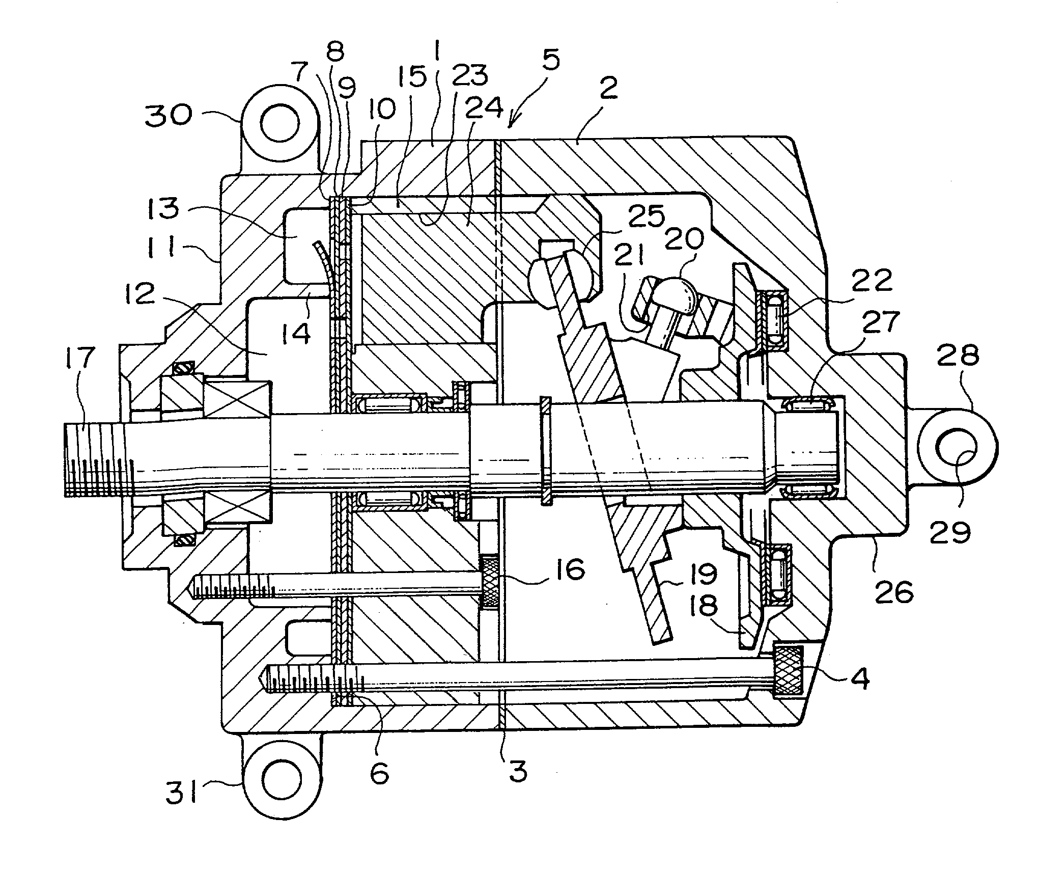
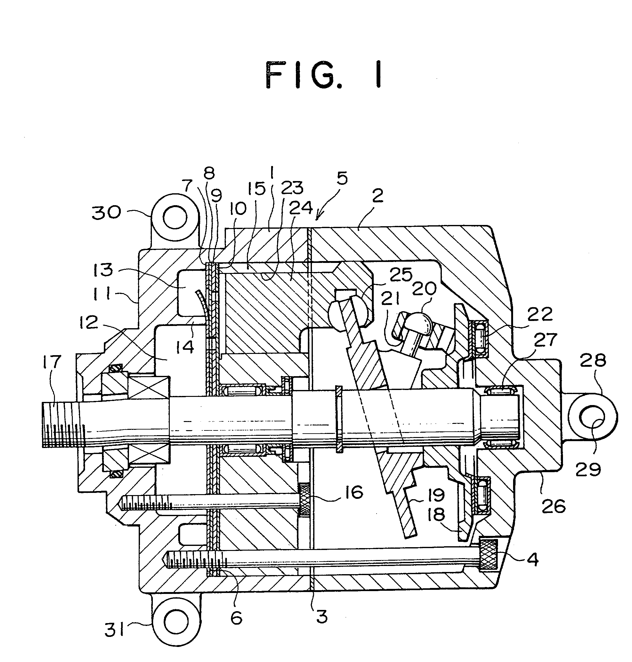
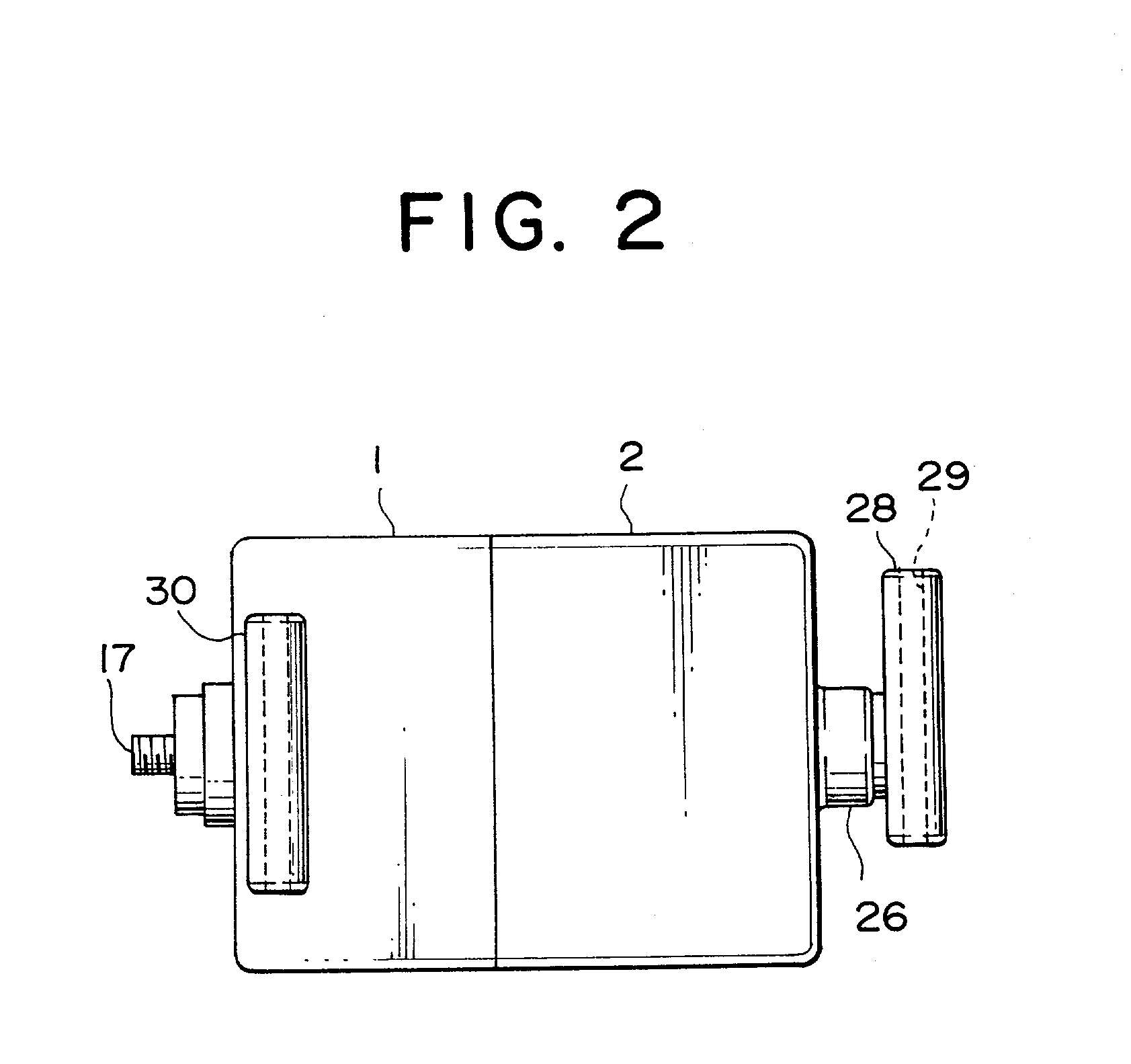
[0014] FIG. 1 shows a structure of a swash plate type variable capacity compressor in accordance with an embodiment of this invention. A front housing 1 and a rear housing 2 are fastened together by means of bolts 4 under the condition that they are coupled with each other through a gasket 3 to thereby form a whole housing 5. A stepped portion 6 is formed within the front housing 1. A retainer forming plate 7, a valve forming plate 8, a valve plate 9 and a valve forming plate 10 are fitted so as to be jointed to this stepped portion 6. An intake chamber 12 and a discharge chamber 13 are defined between the retainer forming plate 7 and a rear end wall portion 11 of the front housing 1 so as to be apart from each other through a partitioning wall 14.

[0015] Also, a cylinder block 15 is fitted so as to be jointed to the valve forming plate 10 within the front housing 1 and is fi...


PUM


Abstract

A compressor includes a housing having a hollow projection portion, a rotary shaft provided rotatably within the housing, a piston reciprocating in accordance with rotation of the rotary shaft for sucking and discharging refrigerant, a bearing disposed within the projection portion of the housing for rotatably supporting one end of the rotary shaft and an attaching leg portion formed on an outer surface of the projection portion of the housing. The attaching leg portion is fastened to an engine block, a bracket or the like by using a bolt or the like.

Description

BACKGROUND OF THE INVENTION[0001] 1. Field of the Invention[0002] The present invention relates to a compressor, and more particularly, to a reduction of vibration of a compressor.[0003] 2. Description of the Related Art[0004] In general, in a piston type compressor such as a swash plate type compressor, an intake chamber and a discharge chamber are partitioned from each other by means of a partitioning wall in a housing, and a cylinder block is disposed so as to face these intake chamber and discharge chamber while intervening a valve plate therebetween. Pistons are disposed slidably within cylinder bores formed in the cylinder block. When the pistons are reciprocated in accordance with the rotation of a rotary shaft, refrigerant within the intake chamber is sucked into the cylinder bore and at the same time, refrigerant is discharged from the cylinder bore.[0005] However, in the case where carbon dioxide is used as refrigerant or the like, the refrigerant is used under the rather ...

Claims


Application Information

Patent Timeline
IPC IPC(8): F04B27/08F04B39/12F04B27/10
CPCF04B27/0891F04B27/1081
Inventor YOKOMACHI, NAOYAKOIDE, TATSUYAMURASE, MASAKAZU
Owner TOYOTA IND CORP
Why Eureka
Try Eureka