System for diagnosing EGR valve, actuator and sensor related failure conditions

a technology of actuators and sensors, applied in the field of diagnostic systems for internal combustion engines, can solve problems such as formation of unwanted emissions

Inactive Publication Date: 2002-09-19
CUMMINS INC
View PDF3 Cites 43 Cited by
  • Summary
  • Abstract
  • Description
  • Claims
  • Application Information

AI Technical Summary

Benefits of technology

0015] Yet another object of the present invention is to provide an EGR valve control system failure diagnosis strategy operable to diagnose a number of different EGR valve control system failures based

Problems solved by technology

When combustion occurs in an environment with excess oxygen, peak combustion temperatures incr

Method used


Image

  • System for diagnosing EGR valve, actuator and sensor related failure conditions
  • System for diagnosing EGR valve, actuator and sensor related failure conditions
  • System for diagnosing EGR valve, actuator and sensor related failure conditions

Examples


Embodiment Construction

[0023] For the purposes of promoting an understanding of the principles of the invention, reference will now be made to a number of preferred embodiments illustrated in the drawings and specific language will be used to describe the same. It will nevertheless be understood that no limitation of the scope of the invention is thereby intended, such alterations and further modifications in the illustrated embodiments, and such further applications of the principles of the invention as illustrated therein being contemplated as would normally occur to one skilled in the art to which the invention relates.

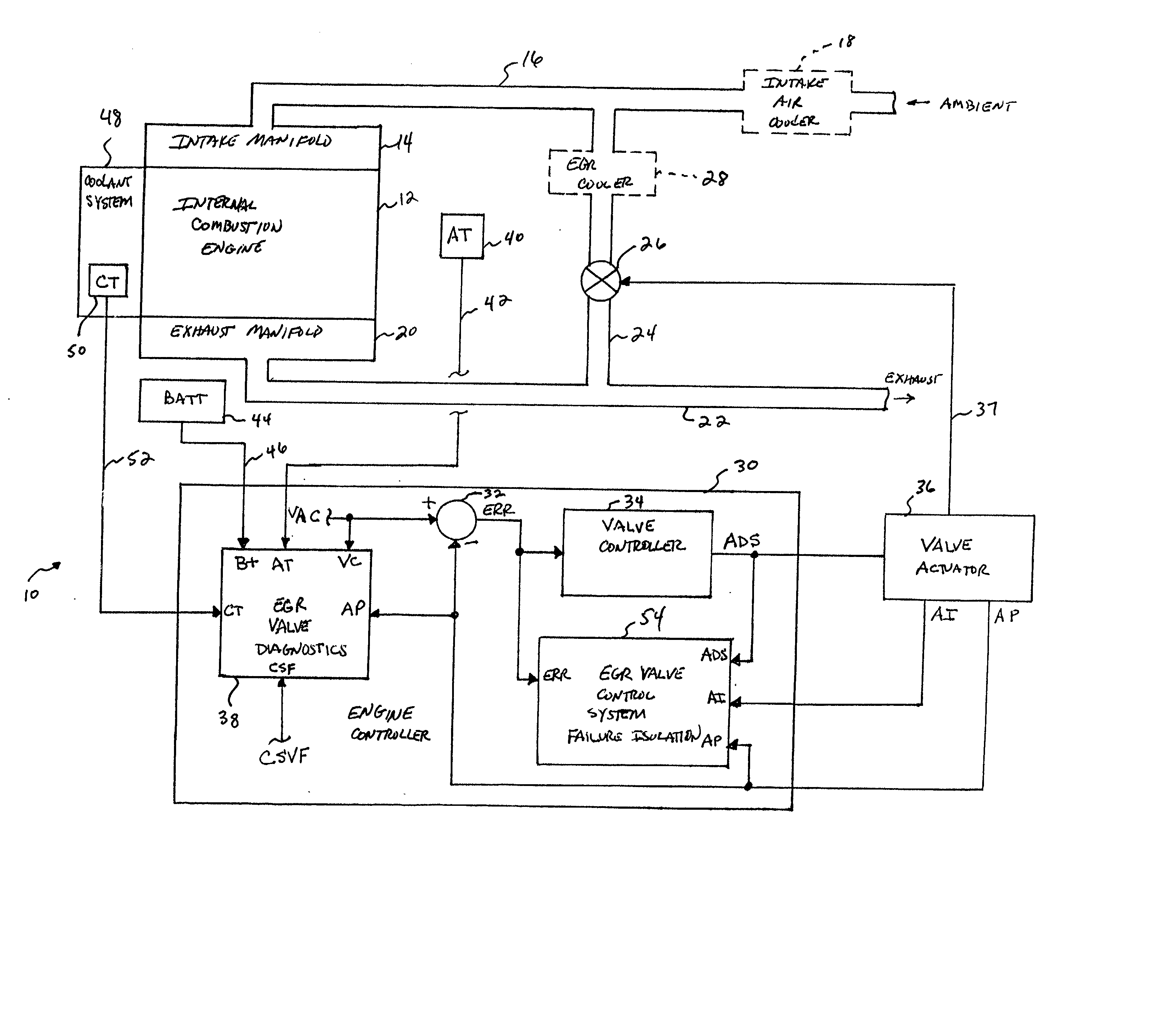
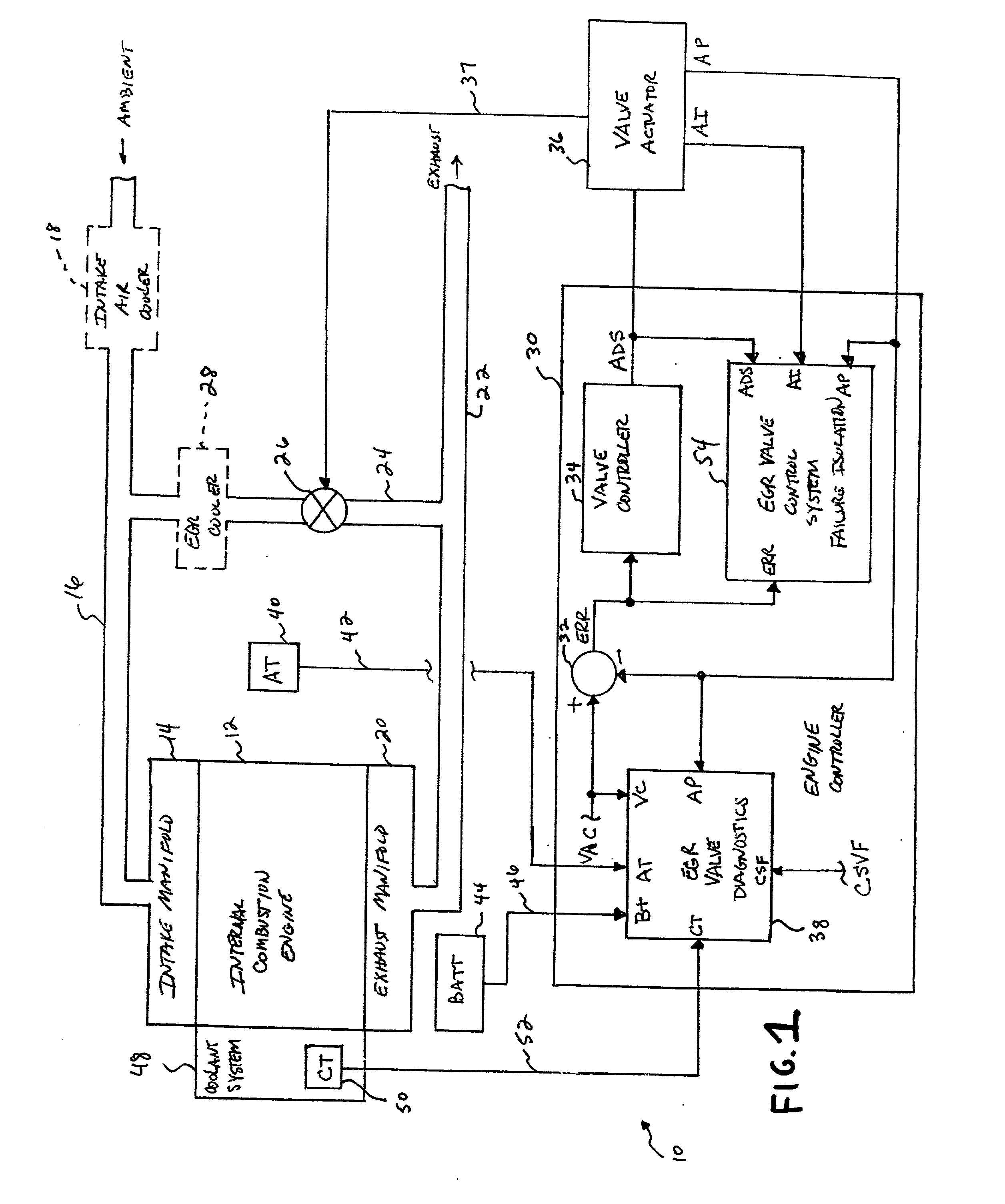
[0024] Referring now to FIG. 1, one preferred embodiment of a system 10 for diagnosing EGR valve, actuator and sensor-related failures, in accordance with the present invention, is shown. System 10 includes an internal combustion 12 having an intake manifold 14 receiving fresh air via intake conduit 16. Optionally, as shown in phantom in FIG. 1, system 10 may include an intake air cooler...


PUM


Abstract

An EGR fault/failure determination system for an internal combustion engine is operable to monitor a number of EGR system operational parameters and diagnose various EGR-related fault and failure statuses therefrom. For example, the system is operable to determine a number of EGR system-related fault and failure conditions by monitoring measured and command EGR position signals to determine EGR valve controller functionality, to monitor response times between fully open and closed EGR valve positions by comparing measured response times to a calibratable response time value, and to monitor in-range EGR position failures associated with fully closed and fully opened EGR valve position values. The system further includes a Kalman filter-based fault/failure isolation feature operable to isolate and identify one or more sources of EGR valve-related faults/failures.

Description

FIELD OF THE INVENTION[0001] The present invention relates generally to diagnostic systems for internal combustion engines, and more specifically to systems for diagnosing fault and failure conditions relating to EGR valves, EGR valve actuators and EGR valve position sensors.BACKGROUND OF THE INVENTION[0002] When combustion occurs in an environment with excess oxygen, peak combustion temperatures increase which leads to the formation of unwanted emissions, such as oxides of nitrogen (NO.sub.x). One known technique for reducing unwanted emissions such as NO.sub.x involves introducing chemically inert gases into the fresh air flow stream for subsequent combustion. By thusly reducing the oxygen concentration of the resulting charge to be combusted, the fuel burns slower and peak combustion temperatures are accordingly reduced, thereby lowering the production of NO.sub.x.[0003] In an internal combustion engine environment, such chemically inert gases are readily abundant in the form of ...

Claims


Application Information

Patent Timeline
IPC IPC(8): F02M25/07
CPCF02B29/0406F02M26/48F02M26/49F02M26/23F02M26/47
Inventor WANG, YUE YUNLI, XIAOQIUSTEPPER, MARK R.YANG, CHANG
Owner CUMMINS INC
Why Eureka
Try Eureka