
Bias flap for side air bags

Inactive Publication Date: 2002-09-19
DELPHI TECH INC
View PDF0 Cites 39 Cited by
  • Summary
  • Abstract
  • Description
  • Claims
  • Application Information

AI Technical Summary

Benefits of technology

[0005] The present invention provides advantages and alternatives over the prior art by providing an air bag assembly having an inflatable air bag cushion and further including a biasing element of flexible character which is released from a stored position upon deployment of the air bag cushion so as to promote the desired deployment path of the air bag cushion between the vehicle occupant and adjacent interior portions of the vehicle. If an occupant to be protected is seated or leaning towards the door panel or other interior side portions of the vehicle, the biasing element assists in the insertion of the cushion between the occupant and the door panel such that the occupant may be moved into a more appropriate position as the air bag cushion is deployed. Such expansion thereby permits the effective expansion of the air bag cushion in the region between the vehicle occupant and the adjacent interior portions of the vehicle at the initial stages of deployment. In the event that the occupant is too large or is seated too close to the door panel to permit effective repositioning through insertion and expansion of the air bag cushion, the biasing element provides a deflection surface between the occupant and the air bag cushion which permits the air bag cushion to travel along an alternative deployment path generally rearward of the occupant.
[0006] In accordance with a potentially preferred aspect of the present invention, the biasing element may comprise a substantially flat pliable material which may be compactly folded for storage prior to deployment.
[0010] Advantageously, the biasing element according to the present invention provides a highly efficient and cost effective means to obtain the desired positional relation between the side impact air bag cushion and the occupant to be protected without the addition of substantial complexity.

Problems solved by technology

Such desired deployment characteristics may be obstructed in the event that the occupant to be protected is positioned outside the borders of the seating structure or is leaning towards the door of the vehicle structure.
Thus, in such a situation, the benefits of the side impact air bag assembly may not be fully realized due to the fact that premature contact between the cushion and the occupant prevents the full cushioning character of the air bag to be achieved.

Method used


Image

  • Bias flap for side air bags
  • Bias flap for side air bags
  • Bias flap for side air bags

Examples


Embodiment Construction

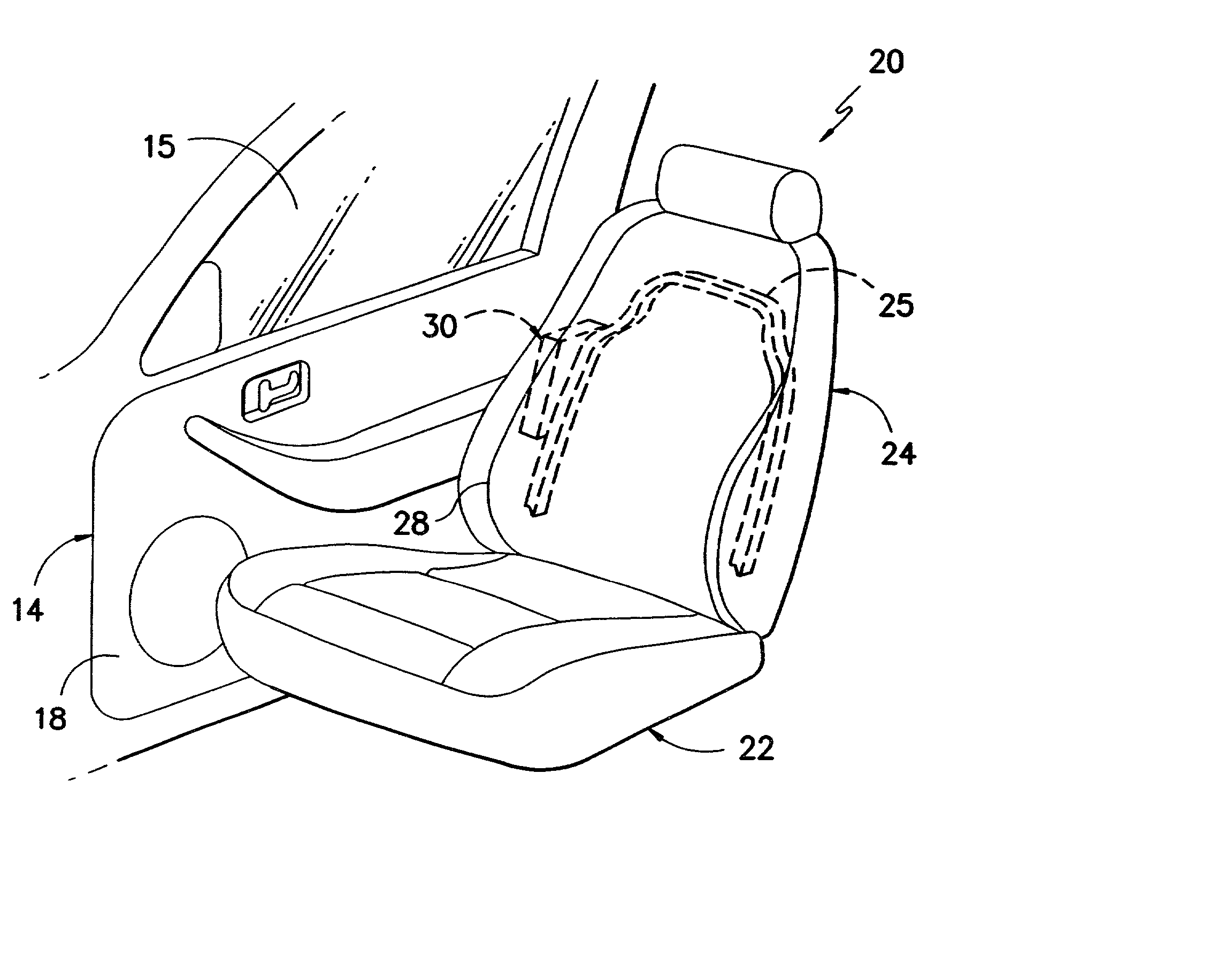
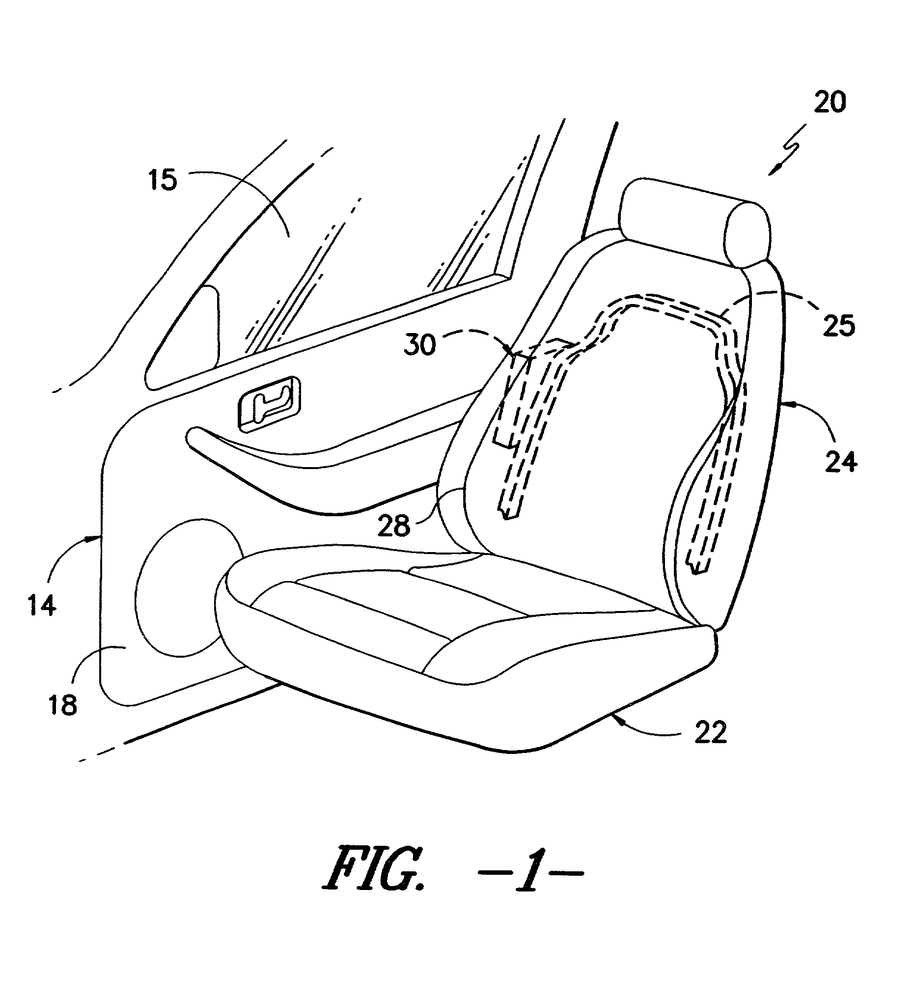
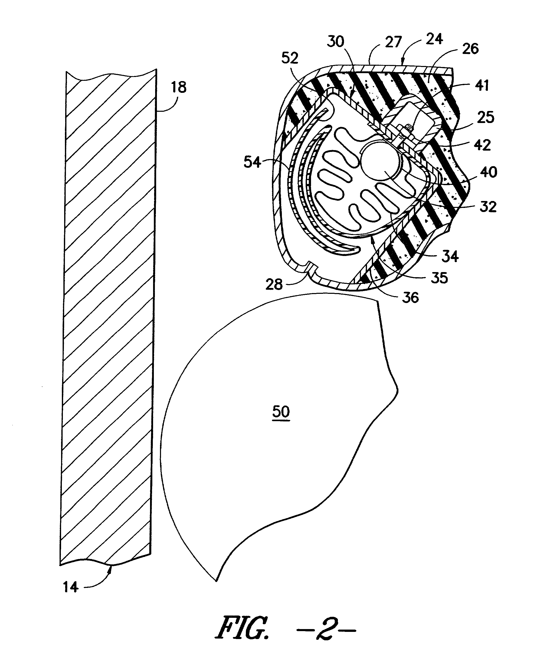
[0018] Referring now to the drawings wherein like reference numerals denote like elements throughout the various views, it is seen in FIG. 1 that a vehicle includes a door 14 having a moveable window 15 mounted thereon. The interior of the vehicle includes an inner door panel 18 and a seat 20 for support of a vehicle occupant (not shown). The seat 20 preferably includes a bottom portion 22 and an upwardly extending back portion 24. The back portion 24 includes a rigid seat frame 25 which is preferably made of metal, and encompassed within the back portion 24. As shown in FIG. 2, the back portion 24 is preferably formed of a foam material 26 covered by a fabric or leather seat material 27. The back portion 24 preferably includes a generally vertically extending seat seam 28 which is proximate to the inner door panel 18.

[0019] As illustrated through reference to FIGS. 2-4, the component parts of an air bag module 30 according to the present invention are preferably located within the ...


PUM


Abstract

An air bag module for protection of an occupant within a vehicle during an impact event. The module includes an inflator for generating an inflation gas, an air bag cushion stored in fluid communication with the inflator such that upon generation of the inflation gas the air bag cushion is deployable substantially to the side of the vehicle occupant between the vehicle occupant and the adjacent interior portions of the vehicle. The air bag module further includes a biasing element of flexible character such as a woven or non woven textile which is folded and stored in overlying relation to the air bag cushion. The biasing element is expelled from its stored position upon deployment of the air bag cushion such that the biasing element is disposed between the occupant and the air bag cushion in leading relation to the air bag cushion along the path of deployment of the air bag cushion between the occupant and adjacent interior portions of the vehicle.

Description

TECHNICAL FIELD[0001] This invention relates to a vehicle air bag assembly, and more particularly, to an air bag assembly for use in the protection of a vehicle occupant during a side impact event.BACKGROUND OF THE INVENTION[0002] It is well known in motor vehicles to provide an air bag assembly for the protection of a vehicle occupant. Such air bag assemblies typically include an inflatable cushion structure in fluid communication with a gas emitting inflator. Upon the occurrence of predetermined vehicle conditions, such as deceleration exceeding a certain level, a signal is sent via appropriate sensors to the gas emitting inflator thereby causing the inflator to discharge gas into the air bag cushion forcing the air bag cushion outwardly from a stored position into an operative position between the occupant to be protected and the interior portions of the vehicle against which the occupant might otherwise come in contact. The presence of the inflated air bag cushion between the oc...

Claims


Application Information

Patent Timeline
IPC IPC(8): B60R21/16B60R21/20B60R21/207
CPCB60R21/207B60R2021/161
Inventor LOTSPIH, JOHN ANTHONYHAWTHORN, LAURA ADELLEWINTERS, MARK THOMAS
Owner DELPHI TECH INC
Learn More