Porous metal foil and production method therefor

a technology production method, which is applied in the direction of porous dielectrics, pretreated surfaces, metal pattern materials, etc., can solve the problems of low foil strength, difficult production of long foils, and insufficient high aperture ratio of porous metal foils produced in accordance with these techniques, and achieves high production efficiency, superior properties, and cost-effective

Inactive Publication Date: 2011-12-29
MITSUI MINING & SMELTING CO LTD
View PDF5 Cites 11 Cited by
  • Summary
  • Abstract
  • Description
  • Claims
  • Application Information

AI Technical Summary

Benefits of technology

[0010]The inventors have currently found that implementation of metal plating on a certain type of peelable layer in which cracks are formed makes it possible to obtain a porous metal foil having superior properties in a highly productive and cost effective manner.
[0011]Thus, an object of the present invention is to obtain a porous metal foil having superior properties in a highly productive and cost effective manner.

Problems solved by technology

However, the actual situation is that the porous metal foils produced in accordance with these techniques fail to achieve a sufficiently high aperture ratio due to a concern that the foil strength would be lowered.
In addition, a long foil is difficult to produce, and anode oxidation process had problems with the peelability of the porous metal foil and the stability of the aperture ratio, in that continuous peeling of the foil destroys the oxidized film.

Method used


Image

  • Porous metal foil and production method therefor
  • Porous metal foil and production method therefor
  • Porous metal foil and production method therefor

Examples


examples

[0050]The present invention will be explained in more detail below with reference to Examples.

example a1

Preparation of Porous Metal Foil

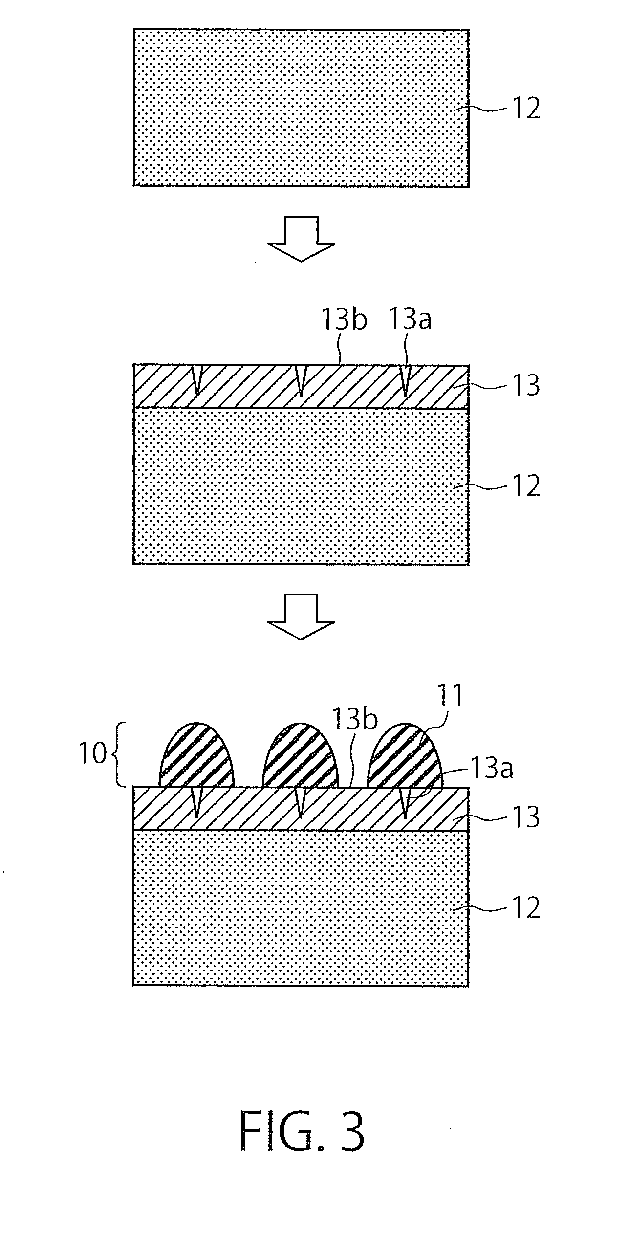
[0051]Copper foil having a thickness of 35 μm was prepared as an electrically conductive substrate. A chromium plating for forming a peelable layer was performed on the copper foil in the following manner. At the outset, the copper foil was immersed for 2 minutes at 40° C. in an acidic cleaner for printed-wiring board (PAC-200 produced by Murata Co., Ltd.) of which the concentration was adjusted to 120 ml / L with added water. The copper foil thus cleansed was immersed in 50 ml / L sulfuric acid at room temperature for 1 minute to be made acid-activated. The acid-activated copper foil was immersed in a chromium plating bath in which 180 g / L Econo-Chrome 300 (produced by Meltex Inc.) and 1 g / L pure concentrated sulfuric acid were dissolved, and was subjected to a chromium plating for 15 minutes under the conditions of a temperature of 45° C. and a current density of 20 A / dm2. The copper foil on which the chromium plating was formed was washed with water an...

example a2

Observation on Porous Metal Foil

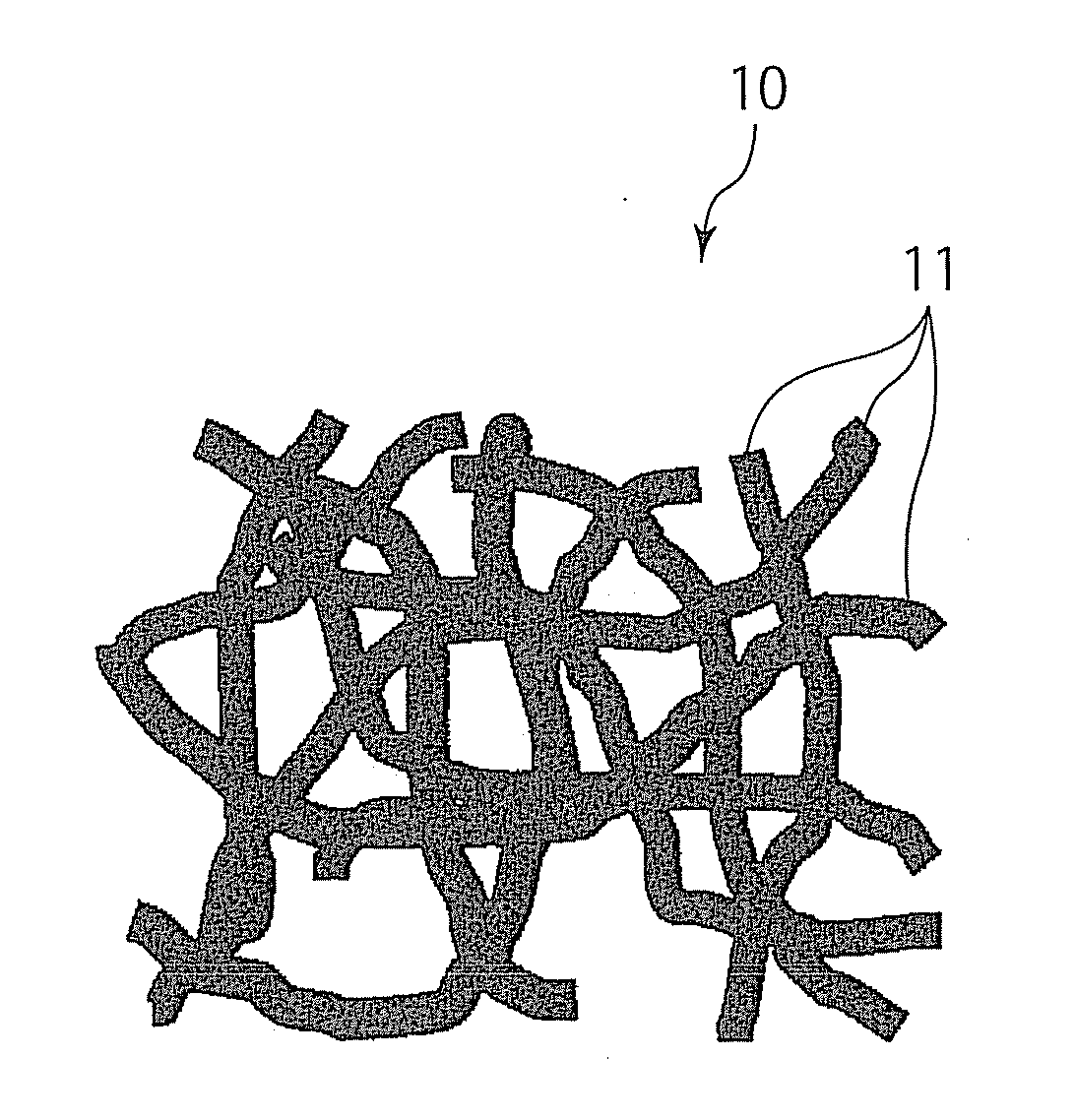
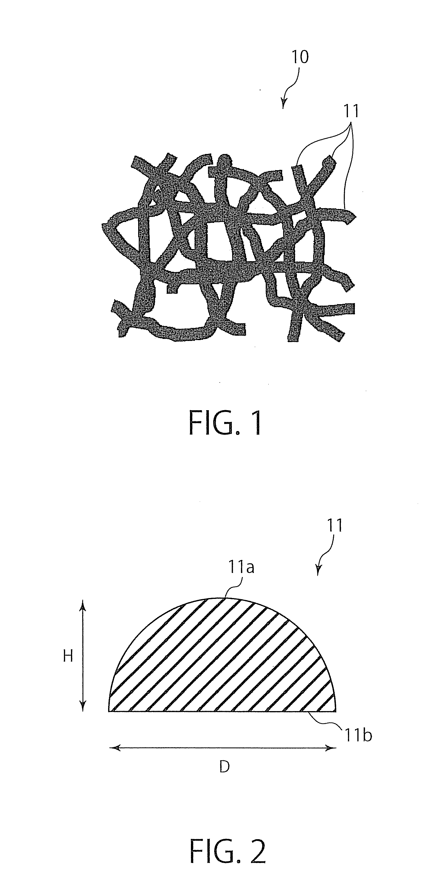
[0053]The porous metal foil obtained in Example A1 was observed by a field emission-scanning electron microscope (FE-SEM) from different angles. At the outset, the side which had not been in contact with the peelable layer of the porous metal foil (hereinafter, growth side) was observed from straight above (at a tilt angle of 0°) and obliquely above (at a tilt angle of 45°) to obtain images shown in FIGS. 4 and 5, respectively. After the porous metal foil was turned back, the other side which had been in contact with the peelable layer of the porous metal foil (hereinafter, peelable side) was also observed from straight above (at a tilt angle of 0°) and obliquely above (at a tilt angle of 45°) to obtain images shown in FIGS. 6 and 7, respectively. As is clear from these figures, beaded irregularities derived from the spherical parts of the metal particles was observed on the growth side, while a plane derived from the bottom part of the metal particle...


PUM

PropertyMeasurementUnit
diameteraaaaaaaaaa
thicknessaaaaaaaaaa
thicknessaaaaaaaaaa

Abstract

A porous metal foil of the present invention comprises a two-dimensional network structure composed of metal fibers. This porous metal foil has superior properties and can be obtained in a highly productive and cost effective manner.

Description

CROSS-REFERENCE TO RELATED APPLICATION[0001]This application claims priority to Japanese Patent Application No. 2009-276649 filed on Dec. 4, 2009, the entire content of which is incorporated herein by reference.TECHNICAL FIELD[0002]The present invention relates to a porous metal foil and a method for producing the porous metal foil.BACKGROUND ART[0003]In recent years, lithium-ion secondary batteries and lithium-ion capacitors have been drawing attention as electric storage devices for use in mobile electronic devices such as mobile phones or laptop personal computers, electric vehicles, and hybrid vehicles. As anode current collectors for such electric storage devices, porous metal foils are used or are being considered for use. This is because making the foil porous provides benefits such that the weight of the foil can be reduced (to improve fuel consumption in automobiles), that adhesive power of an active material can be improved by anchoring effect making use of the pores, and ...

Claims


Application Information

Patent Timeline
Patent Type & Authority Applications(United States)
IPC IPC(8): B32B5/18B05D5/12B05D3/00B32B3/26C25D1/08C25D1/10H01G11/06H01G11/66H01G11/68H01G11/70H01G11/84H01M4/66H01M4/74
CPCC25D1/08Y10T428/12479H01M4/75H01M4/80H01M4/808H05K1/09H05K2201/0116H05K2201/0281H05K2201/0355B01D39/2041B01D2239/10B01D2239/1208C25D1/04Y10T428/12042Y10T428/12431Y10T428/12424H01M4/74C25D3/04Y10T428/249986Y02E60/10C25D1/10B01D39/20
Inventor MATSUNAGA, TETSUHIROWATANABE, HAJIMENISHIKAWA, JOESATO, TETSURO
Owner MITSUI MINING & SMELTING CO LTD
Why Eureka
Try Eureka