Satellite-borne antenna deployable mechanism

A technology for deploying mechanism and spaceborne antenna, which is applied to antennas, foldable antennas, antenna components, etc., can solve the problems of increased mechanism weight, low antenna stiffness, low natural frequency, etc., so as to reduce the impact of the deployment action and reduce the structure. The effect of weight, complexity reduction

Active Publication Date: 2020-05-22
10TH RES INST OF CETC
View PDF13 Cites 10 Cited by
  • Summary
  • Abstract
  • Description
  • Claims
  • Application Information

AI Technical Summary

Problems solved by technology

The antenna and its extension arm need to set multiple locking points. The common solution is to use an independent unlocking mechanism for each locking point, or use a mechanism to realize the rigid linkage of the locking points to unlock. Using multiple independent unlocking mechanisms will increase the unlocking speed. The power demand of the device on the platform, and the rigid linkage will increase the weight of the mechanism, which is not conducive to the small and lightweight design of the product
[0009] Most space-borne deployable antennas use passive deployment power sources (such as torsion springs, pressure springs, etc.). Due to the high flexibility of the antenna system, during the deployment process of the antenna, in addition to the displacement of the rigid body, elastic deformation occurs. The antenna is arranged on the The spring on the node is expanded, and the expansion action must be completed by using two rotating hinges. Its disadvantage is that the structure is heavy and the manufacturing cost is high.
The two movements are coupled with each other, coupled with the influence of hinge clearance and friction, the assembly and adjustment of the antenna are relatively difficult, and the reliability of deployment is relatively low.
The large spaceborne deployable antenna has large size, small rigidity, complex deployment mechanism, and harsh environment; at the same time, due to the small stiffness of the antenna, the natural frequency is very low (fully deployed state)

Method used


Image

  • Satellite-borne antenna deployable mechanism
  • Satellite-borne antenna deployable mechanism
  • Satellite-borne antenna deployable mechanism

Examples


Embodiment 1

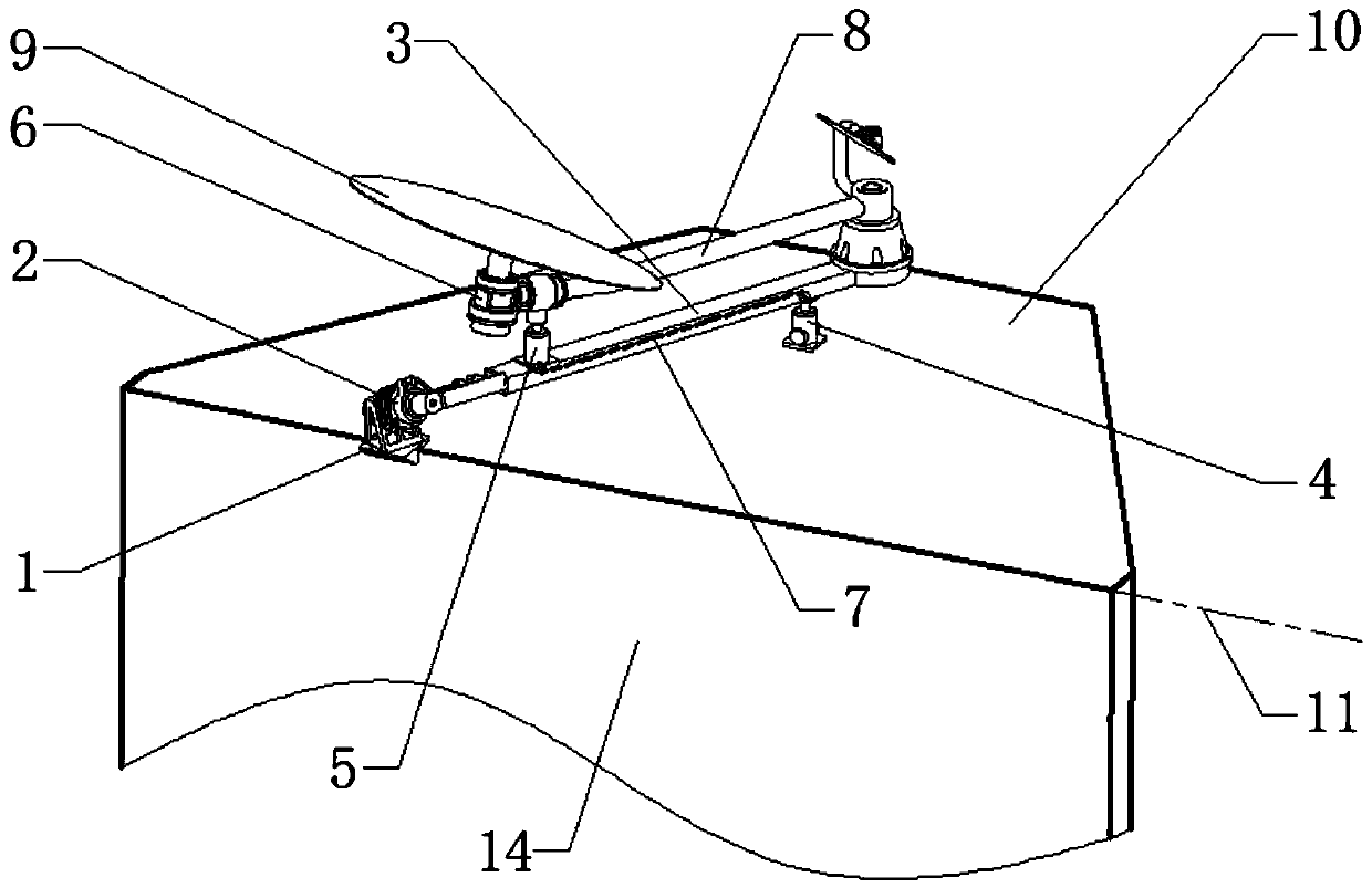
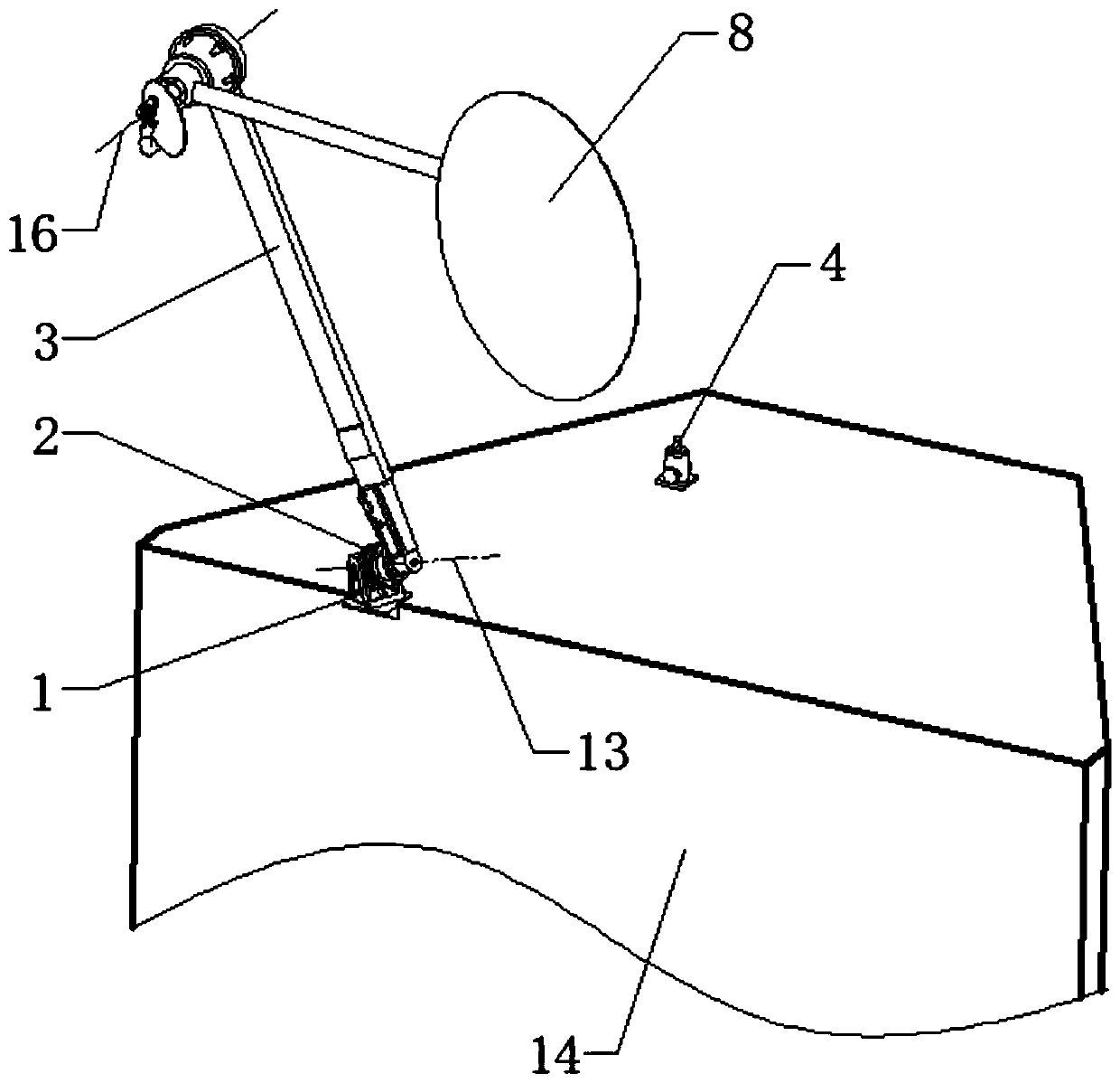
[0028] refer to figure 1 figure 2 . In the preferred embodiment described below, a spaceborne antenna deployable mechanism includes a passively driven synchronous gear transmission joint hinge 2 installed on the satellite body 14 and one end is hinged and fixed to the satellite body through the synchronous gear transmission joint hinge 2 The extension arm 3 on 14, the antenna 8 connected by the antenna rotation shaft 16 at the other end, and the passive drive hinge 6 installed on the antenna reflector 9 at the free end of the antenna 8 connecting rod, is characterized in that: it is installed on the extension arm 3 There is an unlocking mechanism 5 corresponding to the passively driven hinge 6 and a locking mechanism 4 located below the extension arm 3 corresponding to the passively driven hinge 2. When in the state of transmitting and retracting, the antenna reflector 9 is connected to the joint through the passively driven hinge 6 After rotation, it is fixed on the extens...

Embodiment 2

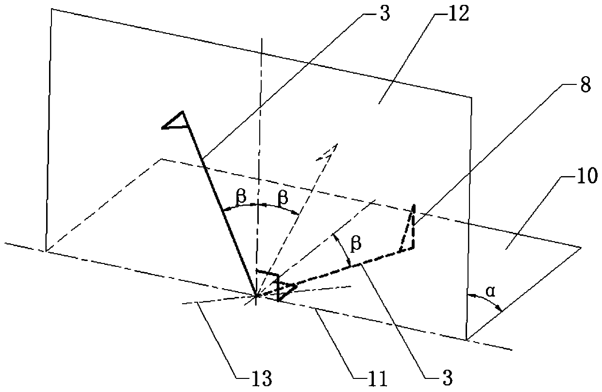
[0034] combine image 3 . The expandable mechanism of the spaceborne antenna in this embodiment is to maximize the space utilization. When the antenna is stored, the antenna needs to be arranged on the fixed surface 10 of the satellite body 14 in the antenna storage state, and the antenna 8 on the end of the extension arm 3 is turned over to a specific angle during work. When the extension arm 3 rotates along the fixed surface 10 in the antenna storage state to the fixed surface 12 in the antenna unfolded state by any angle α, the angle between the vertical line between the extension arm 3 and the initial connection axis of the extension arm is β, and the space angle β is 0°< When β≤90° is arranged, the rotation axis of the antenna 8 is always perpendicular to the fixed surface 12 in the unfolded state of the antenna. At the same time, the direction of the rotation axis 13 of the hinge 2 is determined by the plane method formed by the axis of the extension arm 3 in the two st...

Embodiment 3

[0036] refer to Figure 4 . In the expandable mechanism of the spaceborne antenna in this embodiment, the locking mechanism 4 and the unlocking mechanism 5 have a linkage unlocking structure. The locking mechanism 4 and the unlocking mechanism 5 realize flexible linkage through the cable 7 . A hinge device is respectively arranged at both ends of the drag cable 7, and a torsion spring (or only a hinge near the unlocking mechanism 5) is arranged on the rotation nodes of the two hinges. The direction of the driving force of the torsion spring is shown by the rotation arrow in the figure. After the locking mechanism 4 is unlocked, the right slider moves upwards, and the cable 7 is driven by the elastic potential energy of the torsion spring to move along the unlocking movement direction 15, and the left slider is pulled to move downward, thereby completing the unlocking of the unlocking mechanism 5 and realizing locking The linkage unlocking of mechanism 4 and unlocking mechani...


PUM


Abstract

The invention discloses a satellite-borne antenna deployable mechanism, and aims to provide a deployable mechanism which is high in positioning precision and stable and reliable in work. According tothe technical scheme, an unlocking mechanism corresponding to a passive drive hinge and a locking mechanism which is located below an extension arm and corresponds to a joint hinge rotating shaft areinstalled on the extension arm, and in the storage state, an antenna reflector is connected with a joint through the passive drive hinge to rotate and then is fixed to the extension arm through the unlocking mechanism, the locking instruction is started, the locking mechanism executes an unlocking action, elastic potential energy of the synchronous gear transmission joint hinge drives the extension arm to slowly rotate around the axis of the synchronous gear transmission joint hinge, the locking mechanism triggers the unlocking action of the unlocking mechanism through an inhaul cable connected with the unlocking mechanism, and the inhaul cable is in linkage with the unlocking mechanism to unlock and release the extension arm; after unlocking, the passive driving hinge slowly rotates to apreset angle according to the rotating direction, the unfolding action of the extension arm and the antenna is completed step by step, and the antenna is locked and kept in a working state.

Description

technical field [0001] The invention relates to a mechanism for spaceborne satellites, in particular to a deployable mechanism for a satellite-borne antenna. Background technique [0002] Deployable mechanisms in the aerospace field play an irreplaceable role and have been used as solar panels, displayable space station radar antennas, space radio telescope launch antennas, space operation platforms, and extension arms. The space expandable mechanism is a structural unit composed of flexible cables, rod systems, beams and plates, which are connected by fastening, hinges, sliding fits, folding, etc., and sent into space in a compressed state. It is deployed under the drive of release (energy storage type). The main indicators of the spatially expandable mechanism are the storage rate, quality, deployment reliability, and structural rigidity. The high storage rate enables the mechanism to be folded into a smaller volume and placed in the payload compartment; the light weight...

Claims


Application Information

Patent Timeline
Patent Type & Authority Applications(China)
IPC IPC(8): H01Q1/08H01Q1/12H01Q1/28
CPCH01Q1/08H01Q1/1235H01Q1/288
Inventor 冷献春官正涛
Owner 10TH RES INST OF CETC
Why Eureka
Try Eureka