Gas injection device of gas engine

a gas engine and gas injection technology, which is applied in the direction of engines, machines/engines, mechanical equipment, etc., can solve the problems of reducing engine output, reducing combustion efficiency, and reducing engine output, so as to reduce the number of machining man-hours.

Inactive Publication Date: 2002-10-17
MITSUBISHI HEAVY IND LTD
View PDF3 Cites 34 Cited by
  • Summary
  • Abstract
  • Description
  • Claims
  • Application Information

AI Technical Summary

Benefits of technology

0027] Therefore, the gas streams spouting from the holes of larger opening area located in the upstream side reach the center part of the inner room and air passage of the intake pipe which communicates with the inner room, and the streams spouting from the holes of smaller opening area located in the downstream side do not reach the center part but they flow nearer the wall of the inner room and the intake pipe connected to the inner room. As a result, the fuel gas spouting from the holes can be supplied evenly into the inner room and the flow passage of the intake pipe, which causes uniform mixing of fuel gas with air.
0028] When a plurality of gas entrance openings to introduce the gas into the outer gas chamber are provided symmetrically with regard to the center line of the inner room or when gas pipes of small diameter are connected to the outer gas chamber so that the uniformity of g

Problems solved by technology

If the fuel gas is injected into the intake air just behind the inlet valve before the air flows into the cylinder, the fuel gas enters into the cylinder without mixed with the intake air sufficiently, variation in fuel/air ratio in the combustion chamber is produced, and local fuel rich mixtures are formed which cause knocking due to irregular combustion.
Accordingly, with the prior art mentioned above, pressu

Method used


Image

  • Gas injection device of gas engine
  • Gas injection device of gas engine
  • Gas injection device of gas engine

Examples


first embodiment

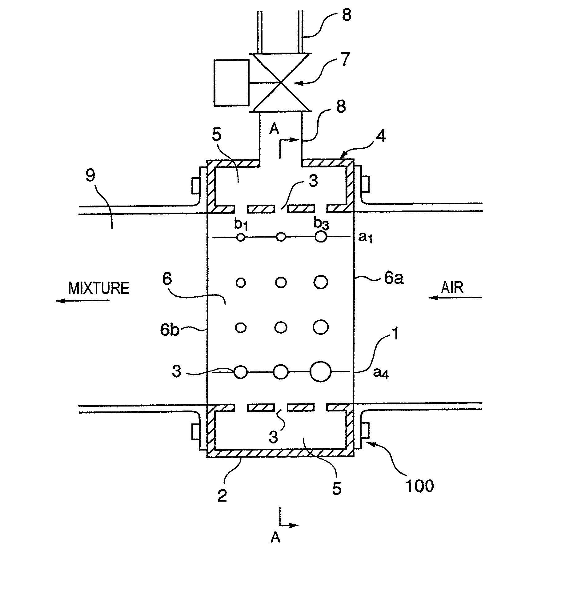
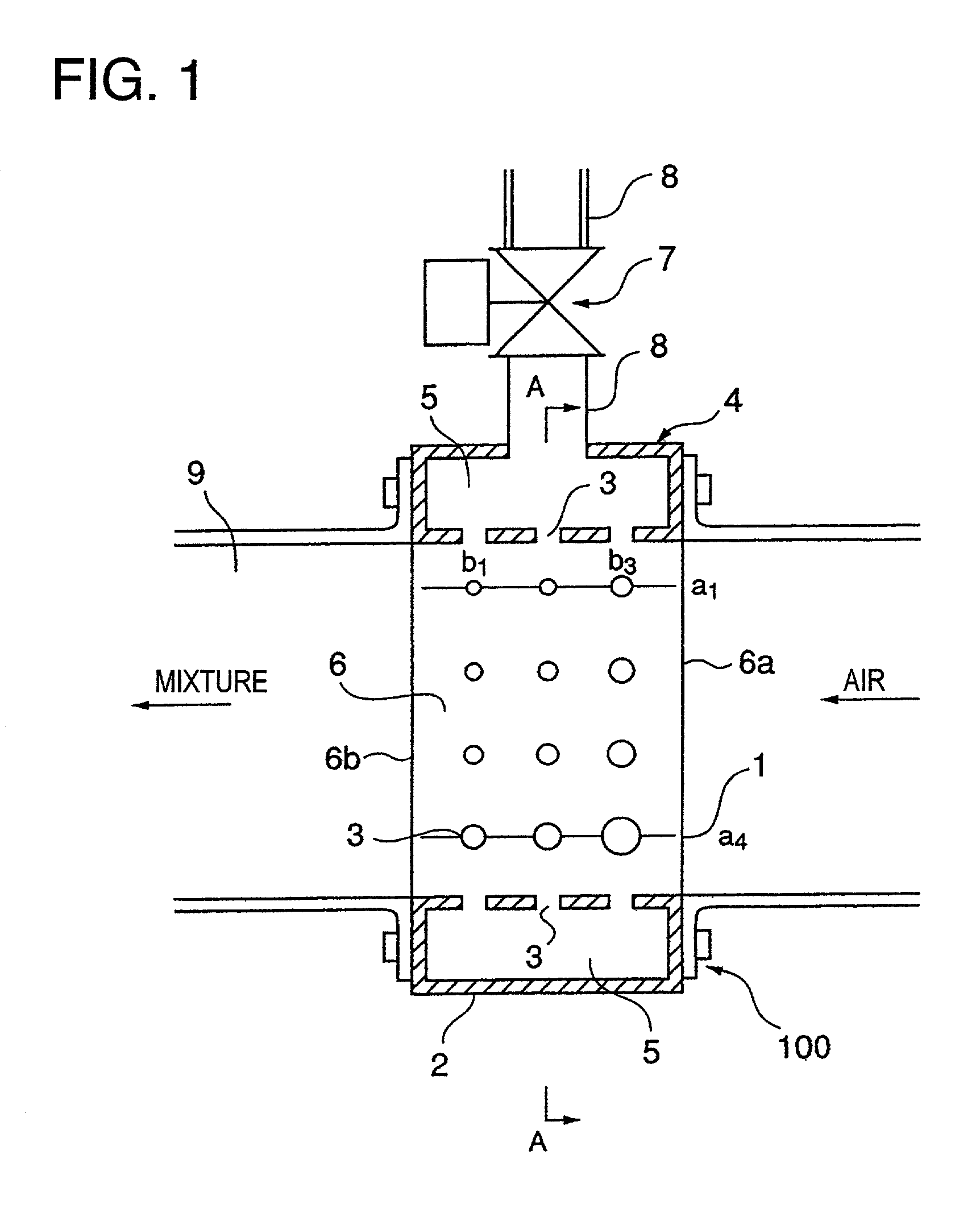
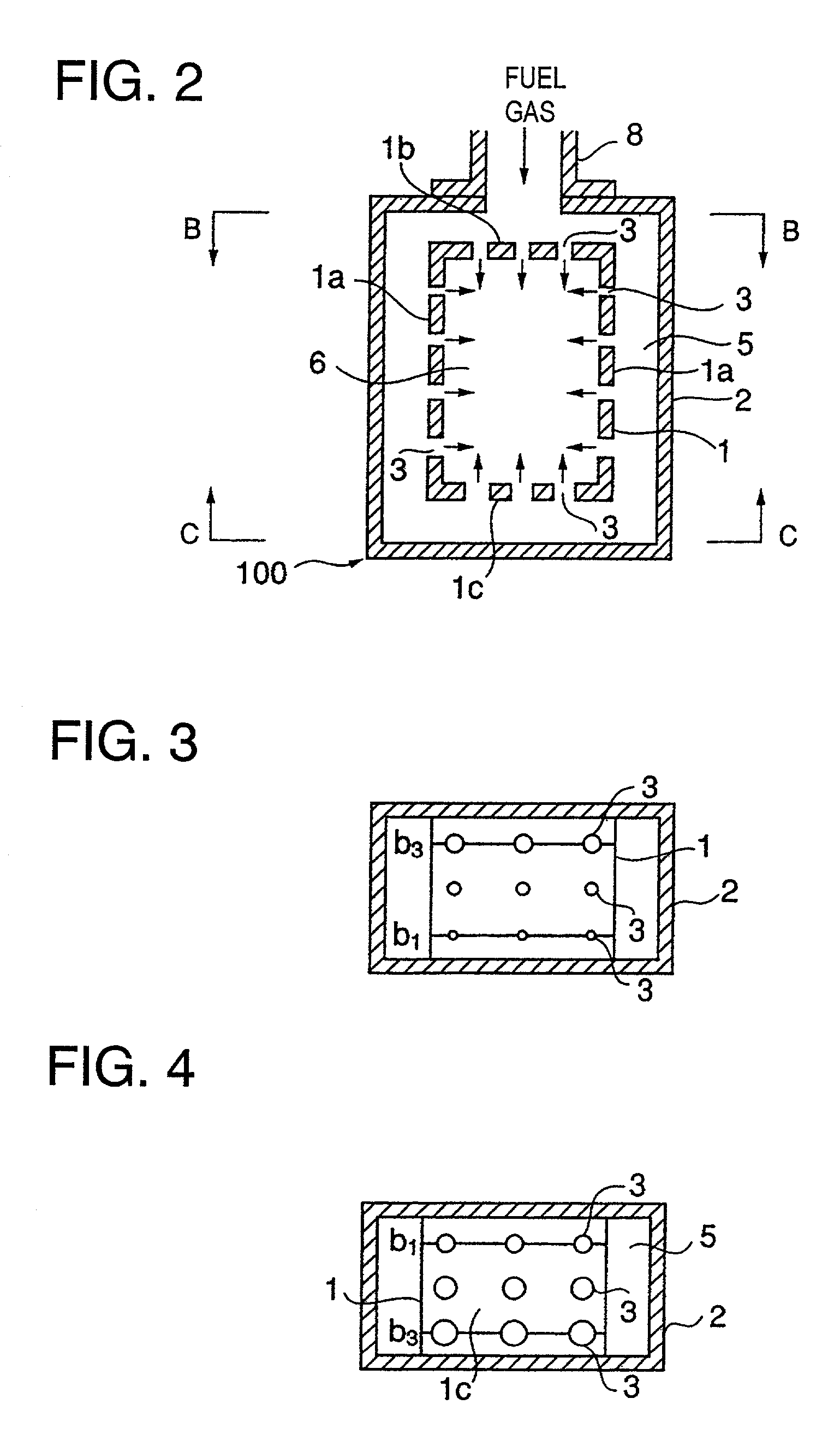
[0080] In the first embodiment, these injection holes 3 are formed in the four sides of the inner wall 1 as shown in FIG. 2 and arranged in a plurality of columns and rows as shown in FIG. 1, 3, and 4(in the example, 3 columns and 4 rows in the side wall, and 3 columns and 3 rows in the upper / lower wall). The injection holes 3 provided in the side walls la(FIG.2) of the inner wall 1 and belonging to the same column are larger in diameter, i.e. larger in opening area as the distance from al row near the header part, at which the gas supply pipe 8 is connected to the outer gas chamber, increases toward a4 row, and the holes belonging to the same row are larger in diameter in the upstream side column b3 than in the down stream side column b1, resulting in that the opening areas of adjacent hole are different from each other.

[0081] Injection holes 3 arranged along the flow passage of the intake air in the upper plate 1b of the inner wall 1 near said head part 4 where an opening is provi...

third embodiment

[0094] the present invention is represented in FIG. 6.about.FIG. 9, in which injection holes 31 of slit-like shape are formed extending in the direction along the sides of the quadrangle of inner wall 1 of the gas nozzle section 100.

[0095] The width of each injection holes 31 formed in the side plate 1a of said inner wall 1 increases with distance from the header part 4 where said gas supply pipe 8 opens as shown in FIG. 9.

[0096] The width of each injection holes 31 formed in the upper plate 1b and lower plate 1c is larger in the upstream side as shown in FIG. 7, and FIG. 8. The configuration of the embodiment is the same as that of the first embodiment except the difference mentioned above, and the similar element as in the first embodiment is marked with the same reference numeral. In the embodiment also the similar effect as the first embodiment is attained.

[0097] A fourth embodiment is shown in FIG. 10, in which a plurality of injection holes are arranged in two parallel side pl...

seventh embodiment

[0103] According to the sixth or seventh embodiment with the upstream header 031 provided upstream-side the gas injection nozzle section 100, the fuel gas of equal pressure is supplied to said gas injection nozzle section 100 by way of the gas supply branch pipe 81, 82, and 83, and the flow rate of the fuel gas flowing in each gas supply branch pipe 81, 82, and 83 is equal.

[0104] According to the seventh embodiment, each of the gas supply pipes 81, 82, and 83 is provided-with an electromagnetic gas supply valve 7, so the injection response at the gas injection nozzle section 100 is good in response to the openings of the electromagnetic gas supply valve 7.

[0105] FIG. 17 shows a first example of the location of the gas injection device, in which each of the gas injection nozzle section 100 provided with the gas supply electromagnetic valve 7 and connected to the gas supply pipe 8 is attached to each intake air branch pipe 9 which branches off from an intake air main pipe 09 to be con...


PUM


Abstract

A gas injection device in which an tunnel-like inner room is formed by surrounding with an inner wall, the inner room is communicated to the intake air flow passage of the intake pipe to allow the intake air to flow through the inner room, the inner wall is surrounded with an outer wall to form between the inner wall and outer wall an outer gas chamber into which fuel gas is introduced, and gas injection holes are provided in the inner wall to permit the gas in the outer gas chamber to sprout out from the injection holes into the air stream flowing through the inner room. The inner room may be partitioned into a plurality of tunnel-like rooms to correspond to the number of the intake air passages in the cylinder head.

Description

[0001] 1. Field of the Invention[0002] The present invention relates to a gas injection device of a gas engine to inject the fuel gas into the intake air flowing through the intake pipe and mix the injected fuel gas with the flowing air for supplying the mixture to the combustion chamber.[0003] 2. Description of the Related Art[0004] Many of gas engines using mainly clean gases such as town gas, etc. adopt pre-mixing type fuel supply method in which the fuel gas is injected into the intake air flowing in the intake pipe of the engine. The mixing of the fuel gas with the intake air is generally done by injecting the fuel gas from the fuel gas injection nozzle protruding in the flowing intake air in the intake pipe. A fuel gas injection device of pre-mixing type using such an gas injection nozzle is disclosed in Japanese Patent Application Publication No. 9-268923.[0005] In the disclosure, a gas injection nozzle is protruding across the intake air passage in the intake pipe of the eng...

Claims


Application Information

Patent Timeline
IPC IPC(8): F02B43/00F02M21/06F02M21/02F02M21/04
CPCY02T10/32F02M21/0278F02M21/042F02M21/0239Y02T10/30
Inventor YAMAMOTO, TAKAYUKIYASUEDA, SHINJI
Owner MITSUBISHI HEAVY IND LTD
Why Eureka
Try Eureka