
Ceramic filter and filter device

Inactive Publication Date: 2002-10-31
NGK INSULATORS LTD
View PDF1 Cites 35 Cited by
  • Summary
  • Abstract
  • Description
  • Claims
  • Application Information

AI Technical Summary

Benefits of technology

0039] The thickness of the partition walls of the honeycomb structure filter is preferably in the range of 50 to 2000 .mu.m, more preferably in the range of 200 to 800 .mu.m. Mechanical strength as the honeycomb structure becomes insufficient when the thickness of the partition wall is less than 50 .mu.m, and effective GSA decreases while increasing the pressure drop for the gas flow when the thickness exceeds 2000 .mu.m. Since the thin wall with a thickness of 50 to 200 .mu.m readily suffers from melting by deformation of the partition wall or holes on the wall by melting, the necessity of the present invention is high with a large melting suppressing effect.
0040] While oxide based materials such as cordierite, mullite, alumina and zirconium phosphate, carbide based materials such as SiC and nitride based materials such as Si.sub.3N.sub.4 may be favorably used for the filter material, the depletion preventive effect becomes the largest by using a filter comprising cordierite that is reactive to the alkali metals and alkali earth metals.
0041] The preferable relation between the pre-filter and ceramic filter will be described hereinafter when the pre-filter is provided as in the second filter device according to the present invention. While the particulate containing ash sources is selectively removed by using the pre-filter, it is possible to further improve selectivity by taking advantage of the facts that the particulate containing the ash source usually has a larger particle diameter as compared with the particulate that contains no ash source.
0042] For example, it is possible to allow the particulate having a larger particle diameter to separate by filtration with the pre-filter, and to allow the particulate having a smaller particle diameter to

Problems solved by technology

However, the overall system turns out to be complex and large size in the method for removing the particulate by backwash.
Consequently, there is such a problem that the filter is lost by being molten at a temperature lower than the melting point of the filter material due to the reaction of this residue with the material constituting the filter at an elevated temperature during operation of the device or in the regenerative combustion treatment.
The filters comprising oxide ceramic based materials involve severe problems since they are particularly reactive with the ash component.
However, it is a problem for the technology disclosed in JP-A-10-33923 that the overall system becomes complex and large size as in the foregoing backwash component regeneration method due to forced peeling of the ceramic particles on which ash components have been adhered.
The technology disclosed in JP-A-11-210440 involves such a problem that it is difficult to permit only the ash component to pass through the outlet side mesh member selectively from the particulate and the ash component having different particle size distribution with each other, thereby either trap efficiency of the particulate

Method used


Image

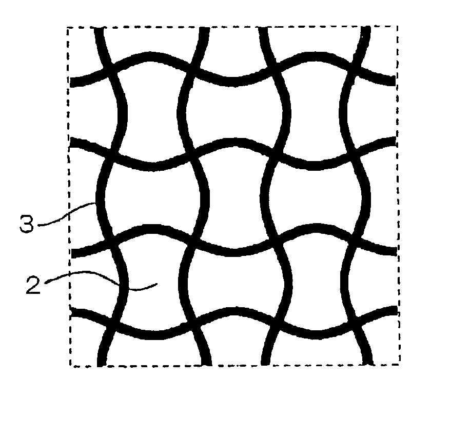
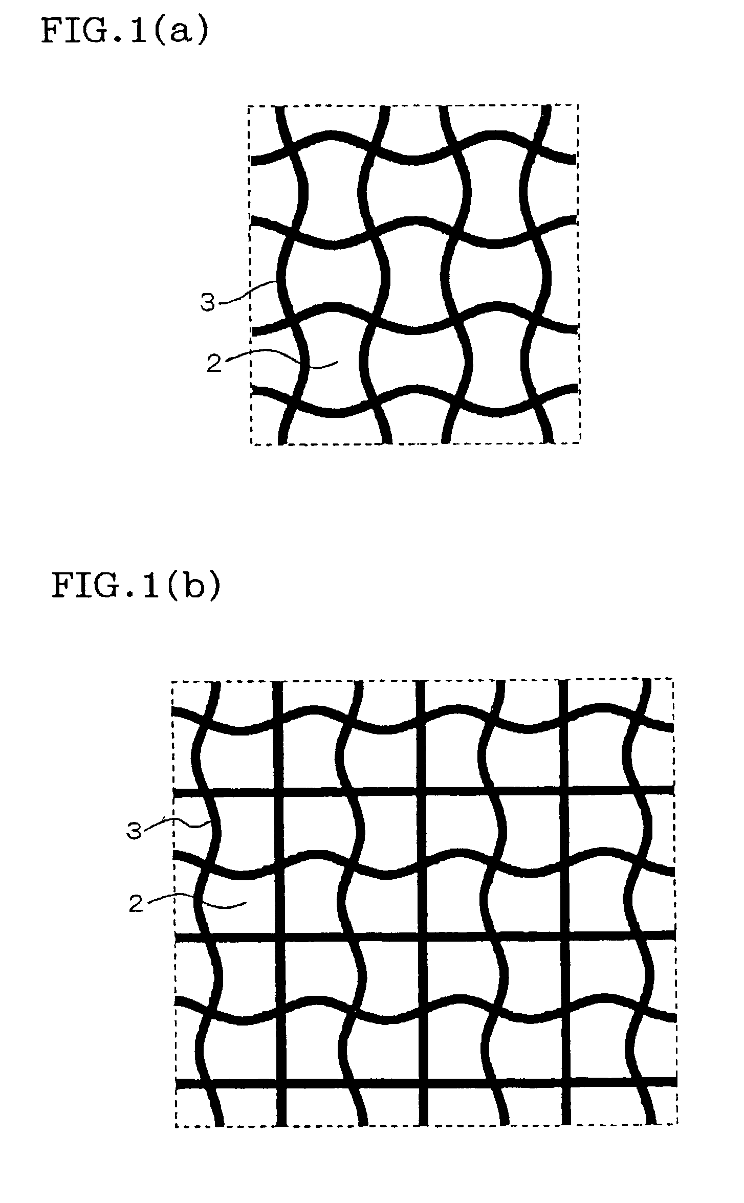
  • Ceramic filter and filter device
  • Ceramic filter and filter device

Examples


example 2

Coating of the Anchor Substance on the Surface of the Ceramic Filter

[0052] A commercially available Al.sub.2O.sub.3 powder (specific surface area: 200 m.sup.2 / g) was immersed in a H.sub.3PO.sub.4 solution and, after stirring with a pot mill for 2 hours, moisture in the powder was evaporated off to dryness. The residual powder was crushed in a dry state followed by firing at 700.degree. C. for 3 hours. An Al.sub.2O.sub.3 sol and water were added again to the powder of .gamma.-Al.sub.2O.sub.3 impregnated with the P component, and the mixture was ground again in a wet state in the pot mill to prepare a wash-coat slurry. Then, the slurry was wash-coated on a small honeycomb piece as the same sample piece as used in Example 1, and the sample piece was dried. The sample piece was fired thereafter at 700.degree. C. for 1 hour in an electric furnace, thereby obtaining a honeycomb sample in which phosphorous P (referred to as an anchor substance) was disposed on the surface of the partition ...

example 3

Filter Device Having the Pre-Filter

[0057] A cordierite honeycomb having a diameter of 144 mm and length of 70 mm, a thickness of the partition wall of 152 .mu.m and a cell density of 62 cells / cm.sup.2 was impregnated with P by the same method as in Example 1 to obtain a pre-filter. A ceramic filter was also prepared by sealing a cordierite honeycomb, having a diameter of 144 mm and a length of 150 mm, a thickness of the partition wall of 305 .mu.m and a cell density of 31 cells / cm.sup.2, of which cells are sealed alternately on an inlet side face and an outlet side face to form a checkered pattern on both sides. The ceramic filter was combined with the pre-filter, and cased in a can having an appropriate shape to obtain a filter device comprising the pre-filter and ceramic filter.


PUM

PropertyMeasurementUnit
Temperatureaaaaaaaaaa
Reactivityaaaaaaaaaa

Abstract

The present invention provides a ceramic filter to be used at a high temperature, and it contains a substance having preferential reactivity with an ash component contained in materials captured by the ceramic filter and not removed by a high temperature treatment such as combustion over the principal component of the ceramic filter; the reaction between said ash component being not removed by a high temperature treatment such as combustion of the filter and remaining accumulated and the filter component to cause melting of the filter being suppressed to attain a long period of service.

Description

[0001] The present invention relates to a ceramic filter being used at an elevated temperature, and being subjected to a high temperature treatment such as combustion for removing accumulated materials captured by the filter upon use, such as the one being represented by a diesel particulate filter (DPF).[0002] A large quantity of fine particles (particulate) mainly comprising carbon are contained in the exhaust gas of a diesel engine. Since the environmental pollution is caused if particulate is discharged into the air, there exists the technique for removing the particulate prior to the discharge of the exhaust gas into the air by installing the particulate trap device including a filter for trapping the particulate in the exhaust system of the diesel engine.[0003] The trapped particulate is gradually accumulated in the filter upon use of the particulate trap device. Therefore, the filter function is regenerated by backwash or combustion of the filter to remove the particulate whe...

Claims


Application Information

Patent Timeline
IPC IPC(8): F01N3/02B01D39/20B01D46/42B01D53/94B01J35/04C04B38/00F01N3/022F01N3/035
CPCB01D39/2068F01N3/022Y10S55/10F01N3/035Y10S55/30F01N3/0222
Inventor NODA, NAOMIYAMADA, KANJI
Owner NGK INSULATORS LTD
Learn More