Battery charger protection circuit

a protection circuit and charger technology, applied in the direction of safety/protection circuits, battery overheat protection, transportation and packaging, etc., can solve the problems of short circuit conditions, damage to one or both batteries, the charger system, and any other electrical load system coupled therewith, and the inability to locate the fus

Inactive Publication Date: 2002-10-31
HOPKINS MFG
View PDF0 Cites 27 Cited by
  • Summary
  • Abstract
  • Description
  • Claims
  • Application Information

AI Technical Summary

Problems solved by technology

Unfortunately, without protection, short circuit conditions could arise wherein the charging battery draws an unsafe amount of current from the charger system, or reverse current conditions could arise wherein the charging battery discharges back into the charger system or charger battery.
In either case, damage can potentially result to one or both batteries, the charger system, and any other electrical load systems coupled therewith.
Unfortunately, once tripped these fuses typically require manual resetting, which

Method used


Image

  • Battery charger protection circuit
  • Battery charger protection circuit
  • Battery charger protection circuit

Examples


Embodiment Construction

.

[0010] A preferred embodiment of the present invention is described in detail below with reference to the attached drawing figures, wherein:

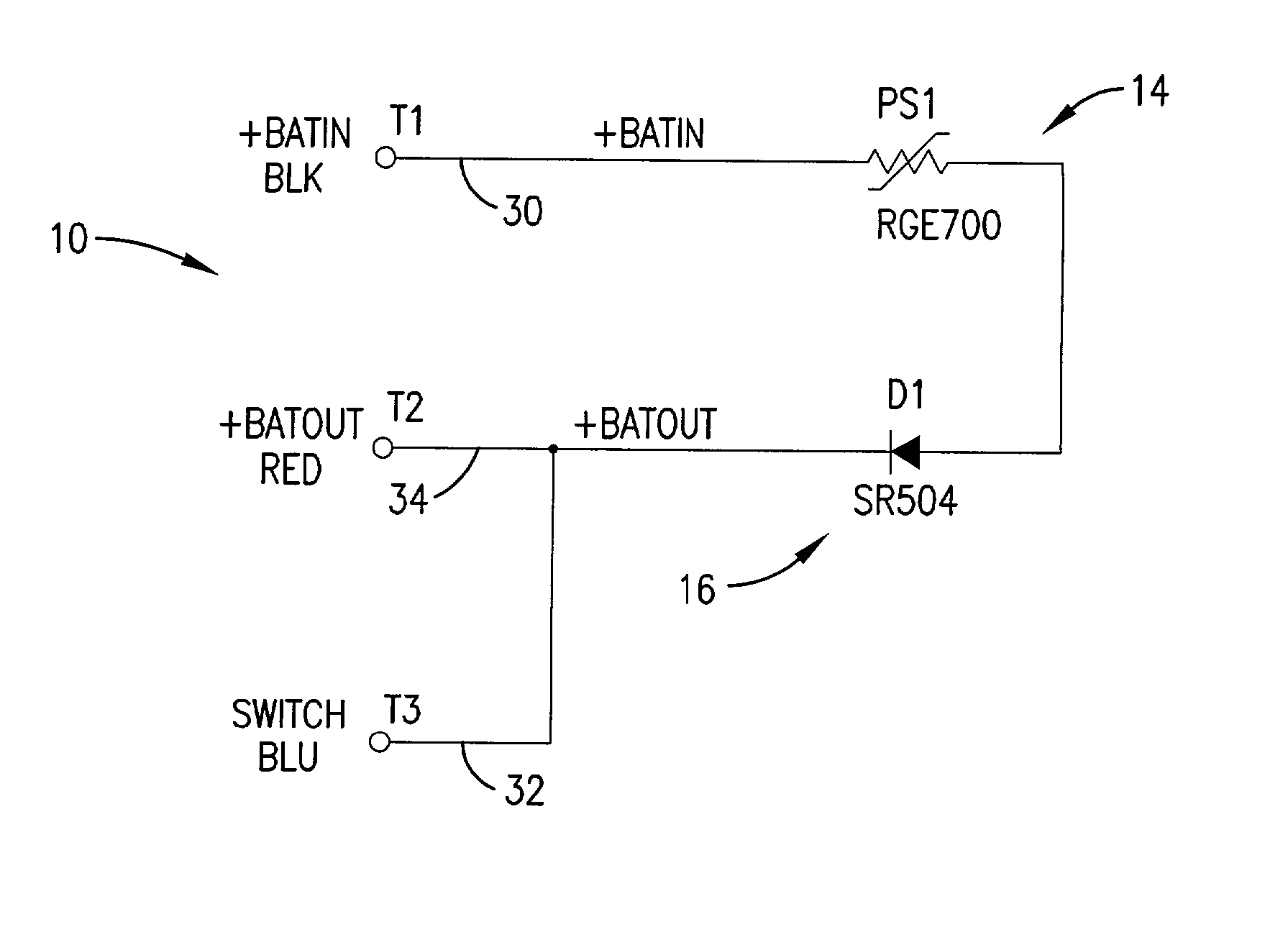
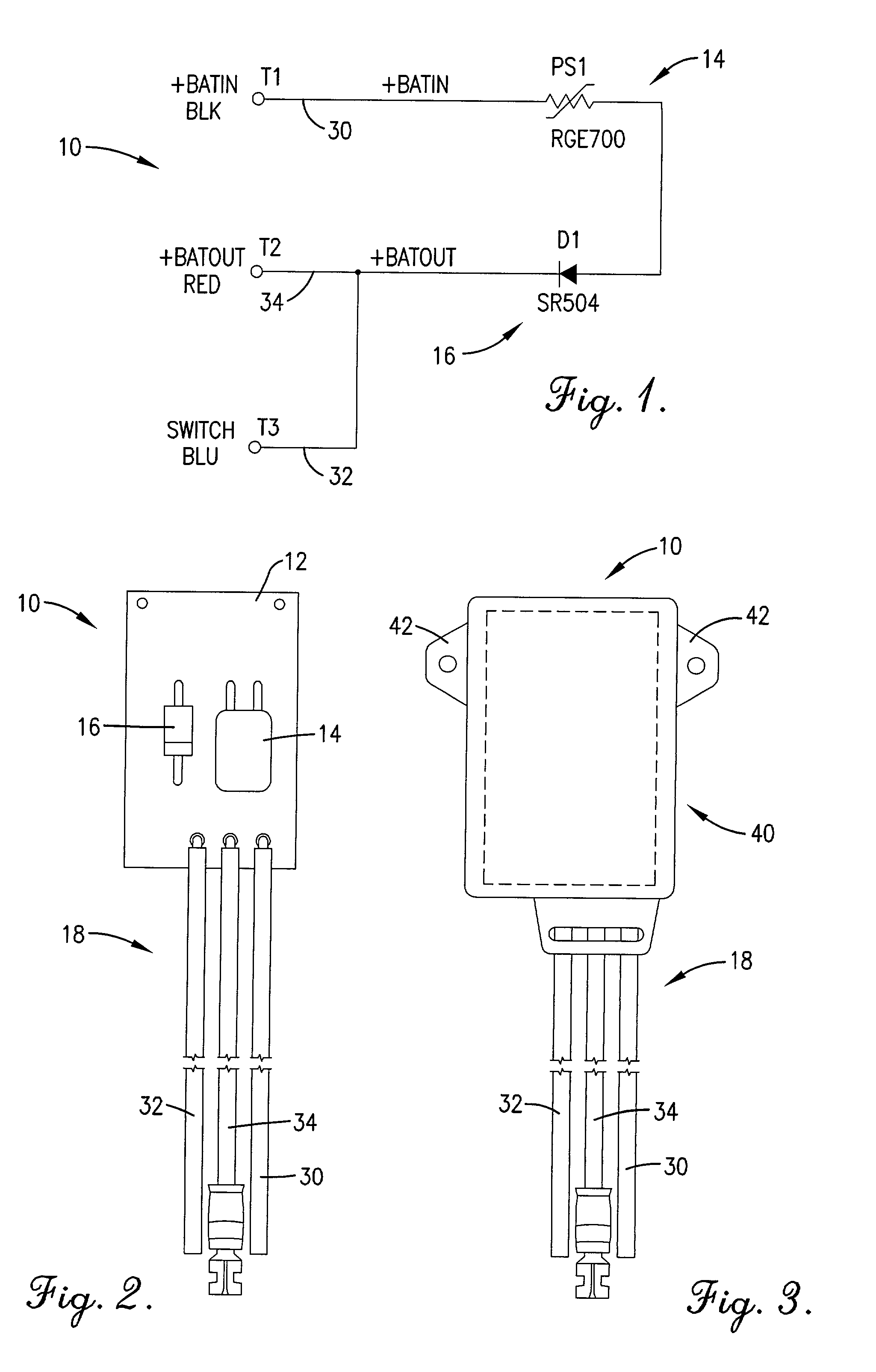
[0011] FIG. 1 is a circuit schematic showing a preferred embodiment of the battery charger protection circuit of the present invention;

[0012] FIG. 2 is a top plan view of the battery charger protection circuit corresponding to the circuit schematic of FIG. 1;

[0013] FIG. 3 is a top plan view of the battery charger protection circuit of FIG. 2 encased within a protective housing; and

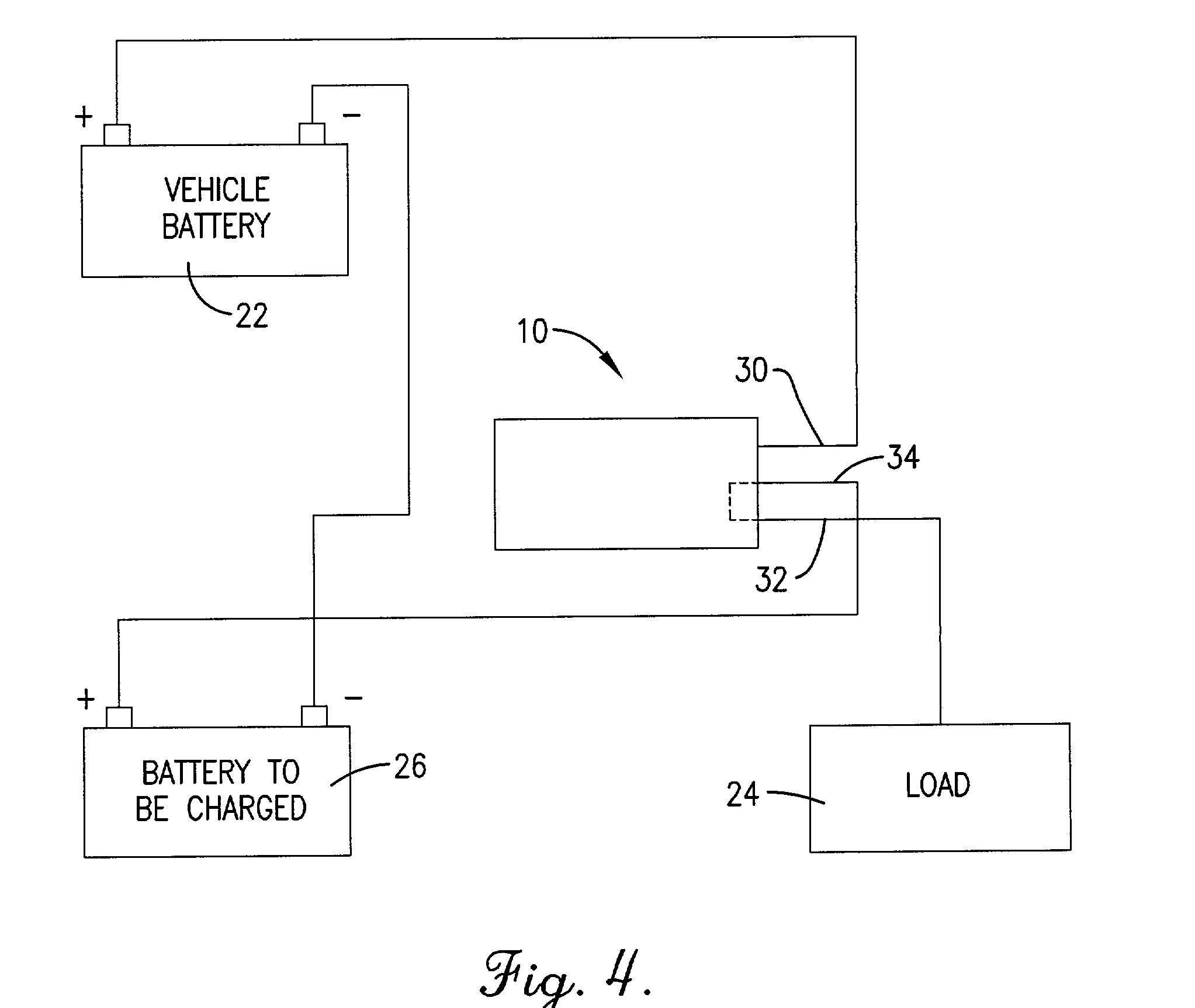
[0014] FIG. 4 is a block diagram showing the battery charger protection circuit incorporated into a preferred embodiment of a battery charger system.

[0015] The drawing figures do not limit the present invention to the specific embodiments disclosed and described herein. The drawings are not necessarily to scale, emphasis instead being placed upon clearly illustrating the principles of the invention.

DETAILED DESCRIPTION OF A PREFERRED EMBODIMENT

[0016] Referring to FIGS...


PUM


Abstract

A battery charger protection circuit (10) interposable between a charger system or charger battery (22) and a lead acid or gel cell charging battery (26) to allow 1-to-1 charging thereof while protecting against short circuit and reverse current conditions. The circuit (10) broadly comprises a printed circuit board (12); a self-resettable fuse (14); a Schottky barrier diode 16; and connection wires (18). The self-resettable fuse (14) includes a temperature-sensitive polymer fuse material operable at a predetermined maximum current, defined by the polymer fuse material's composition, to increase in electrical resistance and thereby reduce current flow.

Description

[0001] 1. Field of the Invention[0002] The present invention is broadly concerned with short circuit and reverse current protection circuits for battery chargers. More particularly, the present invention relates to a battery charger protection circuit incorporating a temperature-sensitive self-resettable fuse providing short circuit protection, and a diode providing reverse current protection.[0003] 2. Description of the Prior Art[0004] It is often desirable to charge an uncharged battery (hereafter charging battery) by, for example, electrically connecting the charging battery either directly to a charger system or indirectly thereto through a second battery (hereafter charger battery). Unfortunately, without protection, short circuit conditions could arise wherein the charging battery draws an unsafe amount of current from the charger system, or reverse current conditions could arise wherein the charging battery discharges back into the charger system or charger battery. In either...

Claims


Application Information

Patent Timeline
IPC IPC(8): H02J7/00
CPCH02J7/0029H02J7/00309H02J7/00304
Inventor LAVINGTON, ROBERT H.WEDEL, JERRY
Owner HOPKINS MFG
Why Eureka
Try Eureka