Process cartridge remanufacturing method

a technology of process cartridges and remanufacturing methods, which is applied in the direction of electrographic process equipment, instruments, optics, etc., can solve the problems of reducing the amount of developer therein with image formation, failing to form an image satisfactory in quality to the user who purchased the process cartridge, and losing the commercial value of the process cartridg

Inactive Publication Date: 2002-10-31
CANON KK
View PDF0 Cites 34 Cited by
  • Summary
  • Abstract
  • Description
  • Claims
  • Application Information

AI Technical Summary

Problems solved by technology

Therefore, the amount of the developer therein gradually reduces with image formation, eventually to a level below which it fails to form an image satisfactory in quality to the user who purchased the process cartridge.
At this point, the process cartridge loses its commercial value.

Method used


Image

  • Process cartridge remanufacturing method
  • Process cartridge remanufacturing method
  • Process cartridge remanufacturing method

Examples


embodiment 1

[0097] (Embodiment 1 of Process Cartridge Remamufacturing Method in Accordance with Present Invention)

[0098] Next, a method for overhauling the cartridge P in this embodiment will be described.

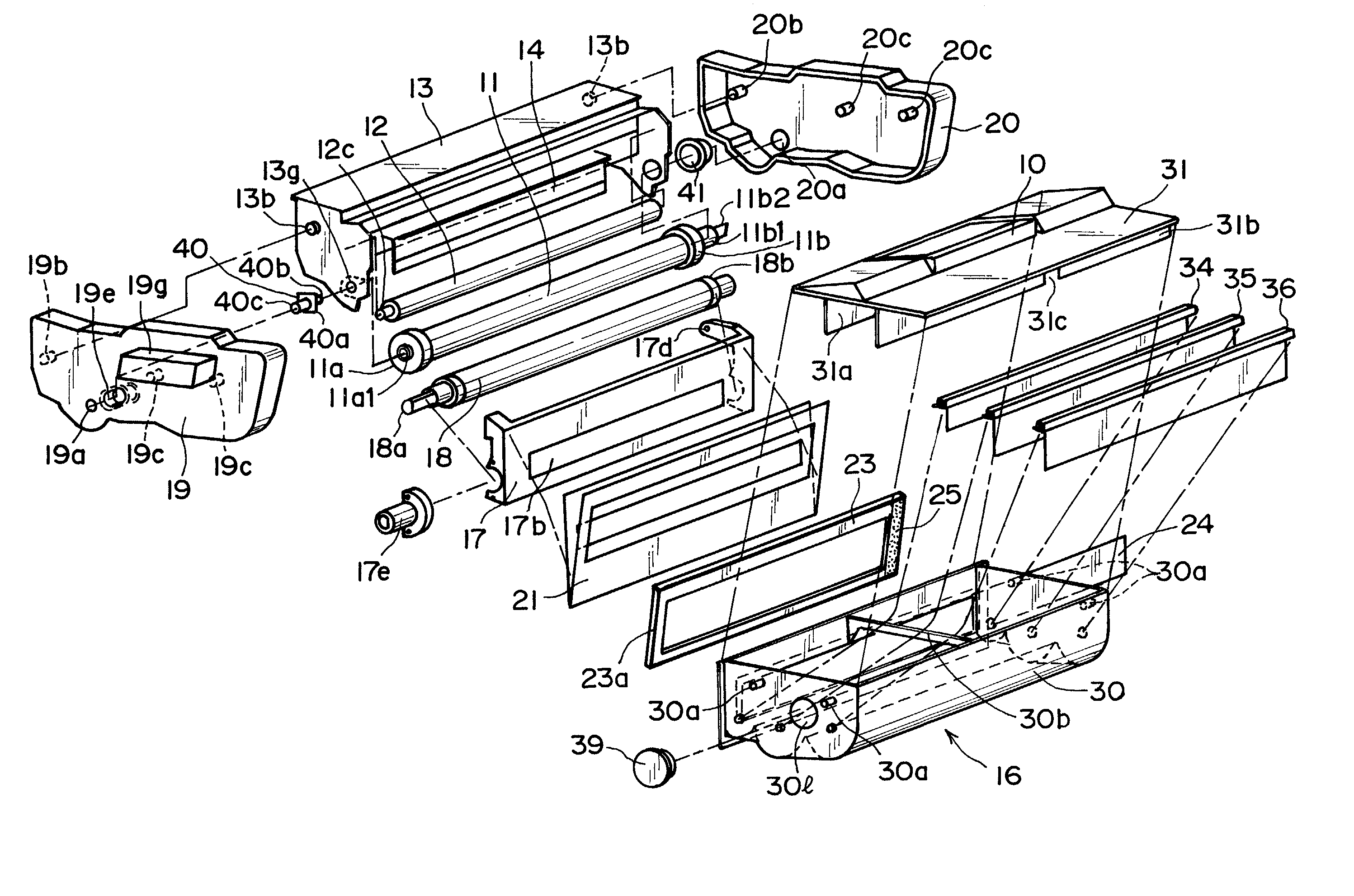
[0099] First, referring to FIG. 22, the shafts 9a and 9b of the shutter 9 fitted in the holes 19h and 20h of the end covers 19 and 20 are removed from the end covers 19 and 20 by being bent in the direction indicated by an arrow mark D, against their resiliency. Incidentally, the shafts 9a and 9b are integral parts of a member engaged with the shutter 9. The shafts 9a and 9b are formed of spring steel.

[0100] Next, the cartridge P is secured to a chuck (unshown) of a milling machine. Then, a milling cutter 60 is positioned in a manner to cut into the welded portions 19i of the seam between the inward edge of the end cover 19 and outward edge of the drum holding frame 13, or the seam between the inward edge of the end cover 19 and outward edge of the frame 30, and is moved along the inward edge ...

embodiment 2

[0106] (Embodiment 2 of Process Cartridge Remanufacturing Method in Accordance with Present Invention)

[0107] Next, the second embodiment of the process cartridge overhauling method in accordance with the present invention will be described.

[0108] Referring to FIG. 22, the shafts 9a and 9b of the shutter 9 fitted in the holes 19h and 20h of the end covers 19 and 20 (end cover 19 side is unshown) are removed from the end covers 19 and 20 by being bent in the direction indicated by an arrow mark D. Then, the shutter 9 is disengaged from the cartridge P (up to this point, procedure is the same as that in Embodiment 1).

[0109] Next, referring to FIG. 26, the cartridge P is secured to the chuck (unshown) of a milling machine. Then, a milling cutter 60 is placed in contact with the peripheral surface of the photoconductive drum 11, and the drum 11 is rotated by rotating the driving force receiving portion 11b2, that is, the end portion of the flange 11b, so that the drum 11 is cut along the...

embodiment 3

[0116] (Embodiment 3 of Process Cartridge Remanufacturing Method in Accordance with the Present Invention)

[0117] The reassembling of the cartridge P, which has been disassembled as described above, will be described in detail, regarding the end covers, with reference to FIGS. 27 and 30. Here, essentially, the relationship between the end cover 19 and drum holding frame 13 will be described. The procedure for cutting off the end cover 19 is the same as that in the preceding embodiments. The procedure thereafter will be as follows.

[0118] The first step is to prepare the end cover 19, frame 13, and frame 30, which have been separated from each other.

[0119] The second step is to prepare an H-shaped spacer 64a, the effective thickness B of which is the same as the width A of the portion 70, in terms of the lengthwise direction of the cartridge, eliminated during the disassembly, or virtually the same as the effective thickness of the spacer 64 as a positioning member (A.apprxeq.B). The w...


PUM


Abstract

A remanufacturing method for a process cartridge detachably mountable to a main assembly of an electrophotographic image forming apparatus, includes (a) an end cover removing step of cutting a fixing portion between the second end cover and the drum frame and cutting a fixing portion between the second end cover and the developer frame, and removing the second end cover at the other longitudinal ends of the drum frame, the developing frame and the developer frame; (b) a drum shaft removing step of removing, at the other ends, a drum shaft rotatably supporting the electrophotographic photosensitive drum at the other ends; (c) a roller separating step of applying forced to the drum frame, the developing frame and the developer frame in directions crossing with a longitudinal direction of electrophotographic photosensitive drum so as to separate the electrophotographic photosensitive drum and the developing roller from each other; (d) a drum removing step of moving the electrophotographic photosensitive drum outwardly from the process cartridge at the other end of electrophotographic photosensitive drum, while keeping the forces applied to the drum frame, the developing frame and the developer frame, so that electrophotographic photosensitive drum is inclined, and then removing the electrophotographic photosensitive drum from the drum frame; (e) a drum mounting step of inserting one end of a new electrophotographic photosensitive drum having at one end a driving force receiving portion for receiving a driving force for rotating the electrophotographic photosensitive drum from the main assembly of the electrophotographic image forming apparatus when process cartridge is mounted to the main assembly of the electrophotographic image forming apparatus, such that driving force receiving portion is exposed outside the drum frame, and inserting the drum shaft at the other end from outside of the drum frame, thus mounting a new drum electrophotographic photosensitive drum to the drum frame; (f) a developer refilling step of opening a filling port provided in the developer accommodating portion, refilling the developer and then closing the filling port; and (g) an end cover mounting step of fixedly mounting a second end cover to the other longitudinal ends of the drum frame, the developing frame and the developer frame.

Description

FIELD OF THE INVENTION AND RELATED ART[0001] The present invention relates to a process cartridge remanufacturing method. Here, a process cartridge means a cartridge in which a minimum of a developing means and an electrophotographic photoconductive member are integrally disposed, and which is removable mountable in the main assembly of an electrophotographic image forming apparatus.[0002] An electrophotographic image forming apparatus includes an electrophotographic copying machine, an electrophotographic printer(for example, LED printer, laser beam printer, and the like), an electrophotographic facsimile, an electrophotographic word processor, and the like.[0003] In an electrophotographic image forming apparatus, a process cartridge system has long been employed. According to this system, an electrophotographic photoconductive member, and a single or plurality of processing means, which act on the electrophotographic photoconductive member, are integrated into a form of a cartridg...

Claims


Application Information

Patent Timeline
Patent Type & Authority Applications(United States)
IPC IPC(8): G03G15/00G03G21/18
CPCG03G21/181G03G2221/1609G03G2215/021G03G2215/00987G03G15/00
Inventor CHADANI, KAZUOMATSUZAKI, HIROOMIMIYABE, SHIGEOSUZUKI, AKIRA
Owner CANON KK
Why Eureka
Try Eureka